Internal EGR cooler
- Summary
- Abstract
- Description
- Claims
- Application Information
AI Technical Summary
Benefits of technology
Problems solved by technology
Method used
Image
Examples
Embodiment Construction
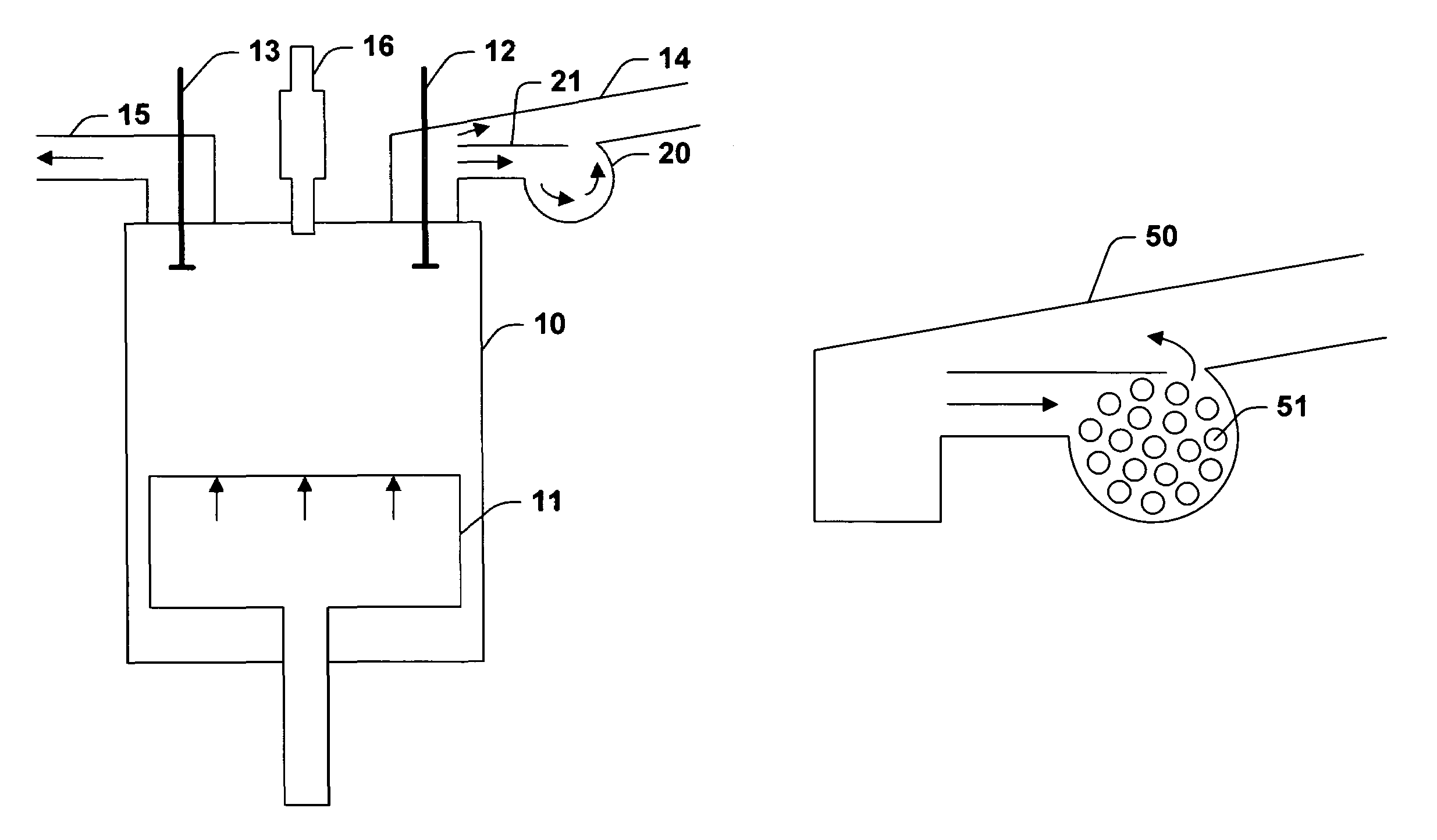
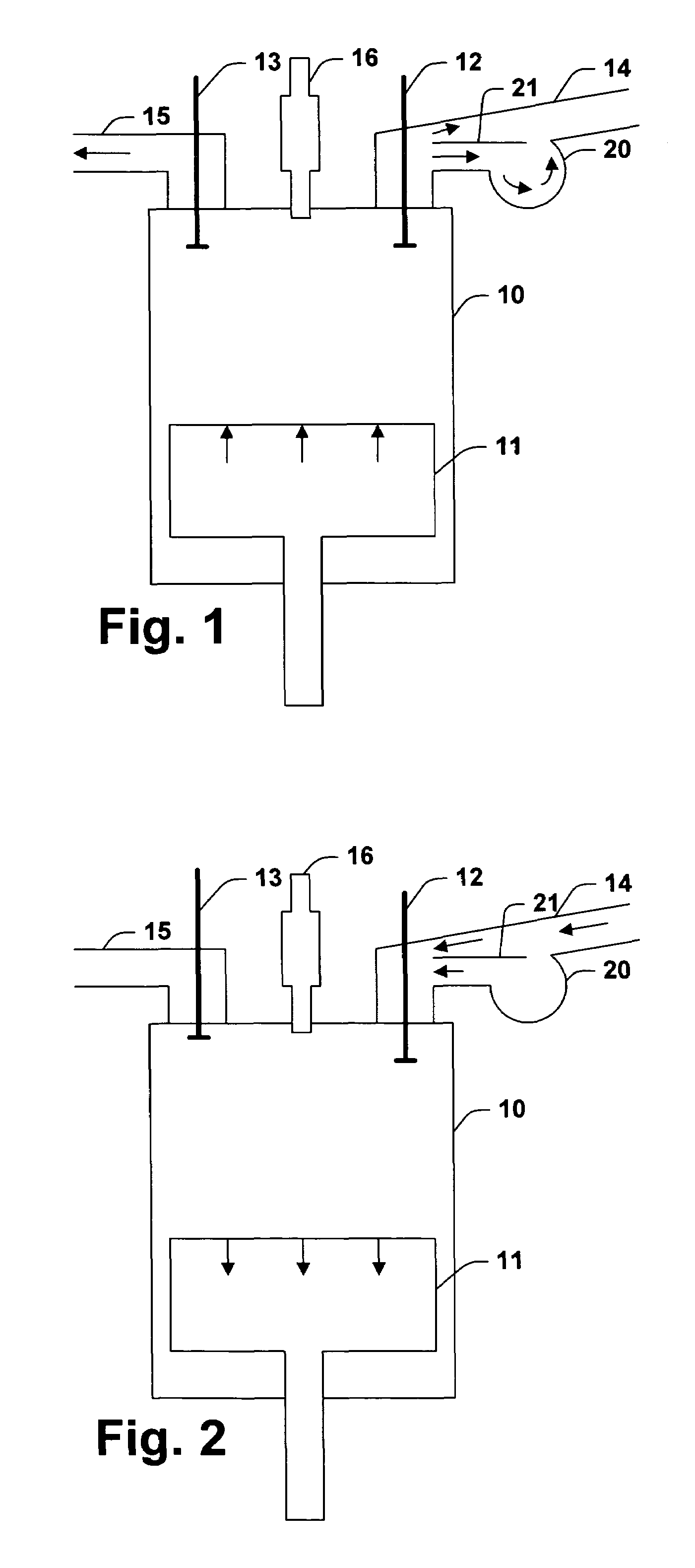
[0021]FIG. 1 illustrates a cylinder 10 of an exemplary engine according to one aspect of the invention in the midst of an exhaust stroke. The cylinder 10 has a piston 11, an intake valve 12, an exhaust valve 13, an intake manifold 14, an exhaust manifold 15, and a fuel injector 16. According to the invention, the intake valve 12 is open during a portion of the exhaust stroke, generally during the early part of the exhaust stroke. Opening the intake valve during the exhaust stroke causes exhaust to flow into the intake manifold 14 where the exhaust mixes with fresh air and is cooled. Cooling may occur before, during, or after mixing. FIG. 2 illustrates the cylinder 10 during an intake stroke. Exhaust released into the intake manifold 14, cooled and mixed with intake air, is drawn into the cylinder 10.
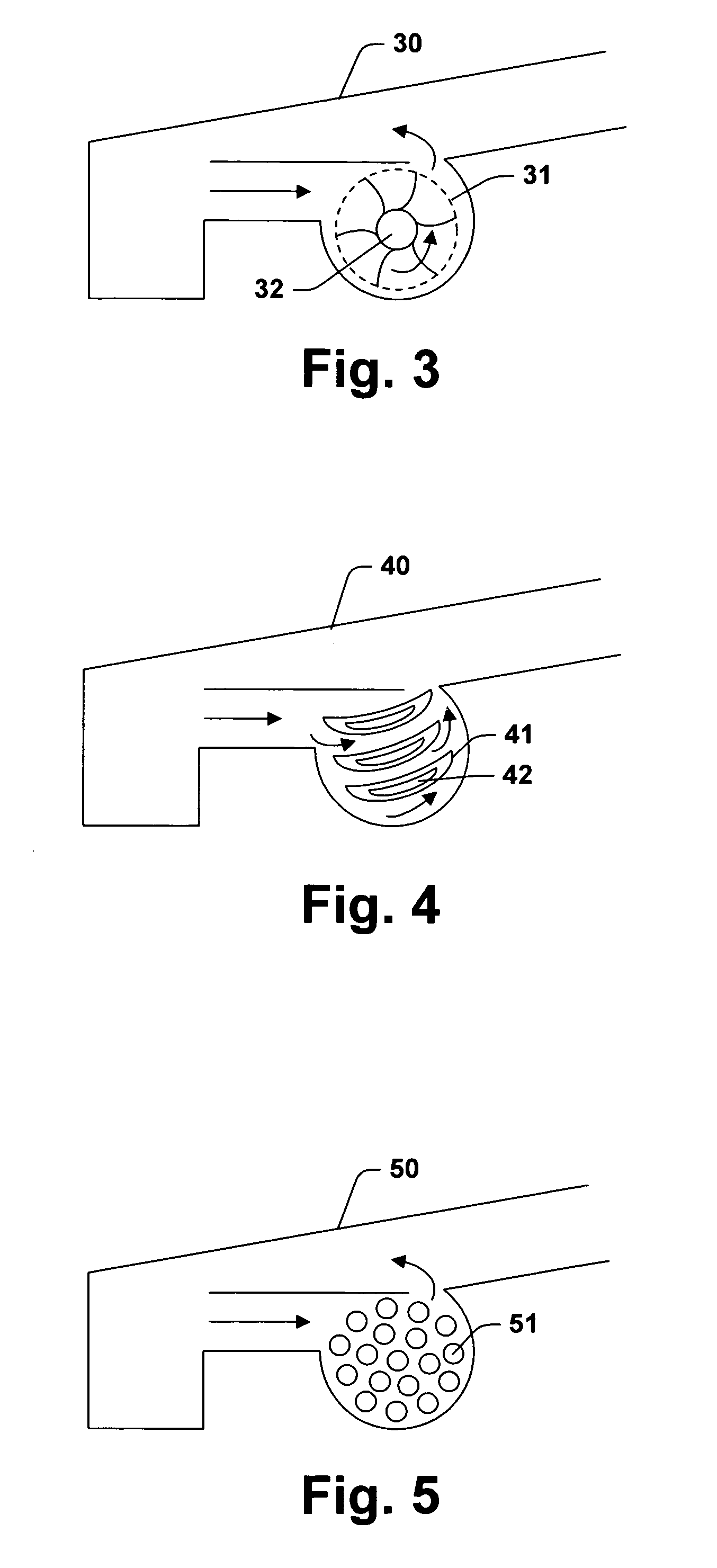
[0022]The intake manifold 14 preferably includes a bulge 20. A bulge can be any swelling of the intake manifold to a size beyond that which is dictated by its function of channeling air ...
PUM
 Abstract
Description
Claims
Application Information
 - R&D
- Intellectual Property
- Life Sciences
- Materials
- Tech Scout
- Unparalleled Data Quality
- Higher Quality Content
- 60% Fewer Hallucinations
Browse by: Latest US Patents, China's latest patents, Technical Efficacy Thesaurus, Application Domain, Technology Topic, Popular Technical Reports.
© 2025 PatSnap. All rights reserved.Legal|Privacy policy|Modern Slavery Act Transparency Statement|Sitemap|About US| Contact US: help@patsnap.com


