
Flood protection barrier

a technology of flood protection and barrier, applied in the direction of building components, applications, wing fasteners, etc., can solve the problems of theft or tampering of many of the known devices, fixtures may detract from the appearance of their premises or otherwise inconvenient,

Inactive Publication Date: 2005-08-23
HELHOLT FLOOD LTD +1
View PDF20 Cites 14 Cited by
  • Summary
  • Abstract
  • Description
  • Claims
  • Application Information

AI Technical Summary

Benefits of technology

[0008]An aim of this invention is to provide a flood protection barrier for a door or other aperture in a building that can be deployed rapidly as and when required, yet leave no (or minimal) fixtures in place while the barrier is not required for use in times of normal weather.
[0011]Advantageously the securing means is carried on the shield. More specifically, the securing means may be entirely carried on the shield. This has a twofold advantage, in that no part of the securing means is left in position on a building when the barrier is not in use, and in that the securing means are unlikely to be misplaced; this being especially important because they may be required for use as a matter of urgency.
[0013]This reduces the likelihood that the securing means will be subject to unauthorised tampering. It is advantageous that the barrier, when deployed, does not prevent closure of the door or window. This may be achieved by providing securing means that cooperate with an outer part of the frame or the reveal adjacent to the frame. Alternatively, in the case of embodiments according to the last-preceding paragraph, the securing means may cooperate with an inwardly directed surface in the region of a recess into which the door or window (as the case may be) is received when closed. Provided that the securing means is suitably dimensioned (i.e. thin enough) it will not prevent closure of the door or window, thereby ensuring that the building upon which the barrier is deployed can be secured.
[0016]Each shield is advantageously formed with a dimension that is greater than a corresponding dimension of the aperture. Such a shield may be placed against an external surface of the aperture, such that water in contact with the shield acts to push the shield into engagement with the external surface, and thereby assist in locating it in place.

Problems solved by technology

However, these typically require permanent installation of fittings (such as mounting channels) to the building in the region of the doorway to which a removable barrier can be connected in use.
While such barriers can provide an effective flood defence, many occupiers do not wish to have permanent fixtures mounted on their premises.
These fixtures may detract from the appearance of their premises or be otherwise inconvenient on a permanent basis, while they are needed for use only in the event of a flood; an event that may happen only once in many years.
It is also apparent that many of these known devices might be subject to theft or tampering whilst in use.
This reduces the likelihood that the securing means will be subject to unauthorised tampering.

Method used


Image

  • Flood protection barrier
  • Flood protection barrier
  • Flood protection barrier

Examples


Embodiment Construction

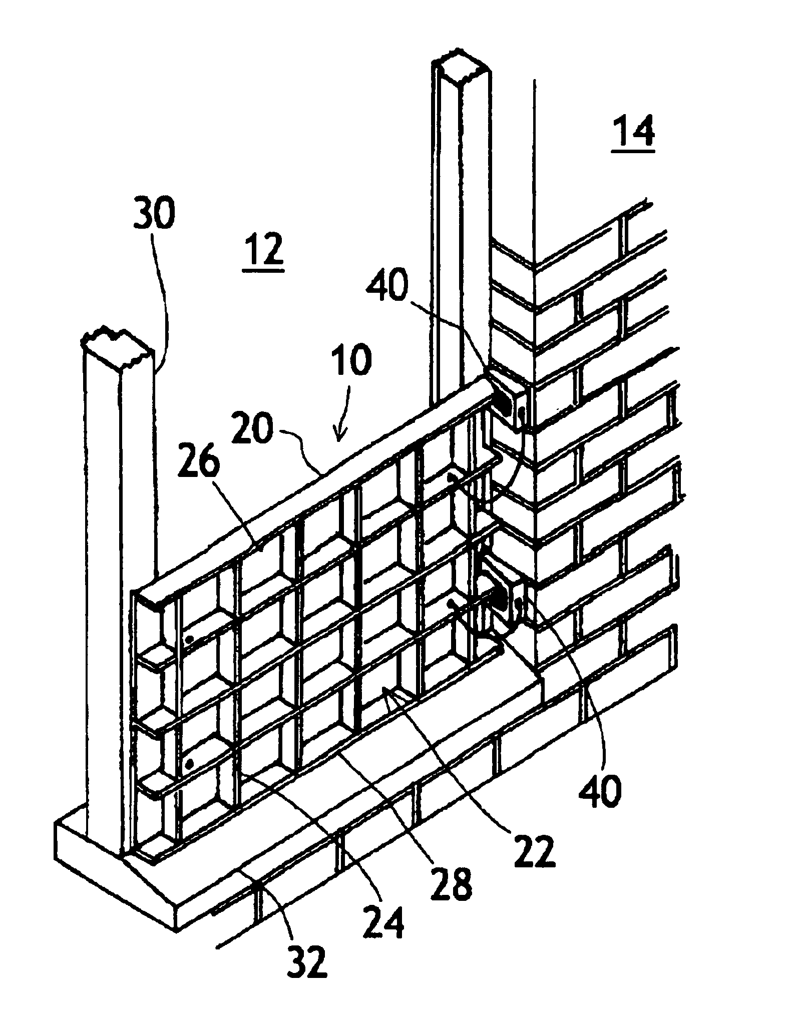
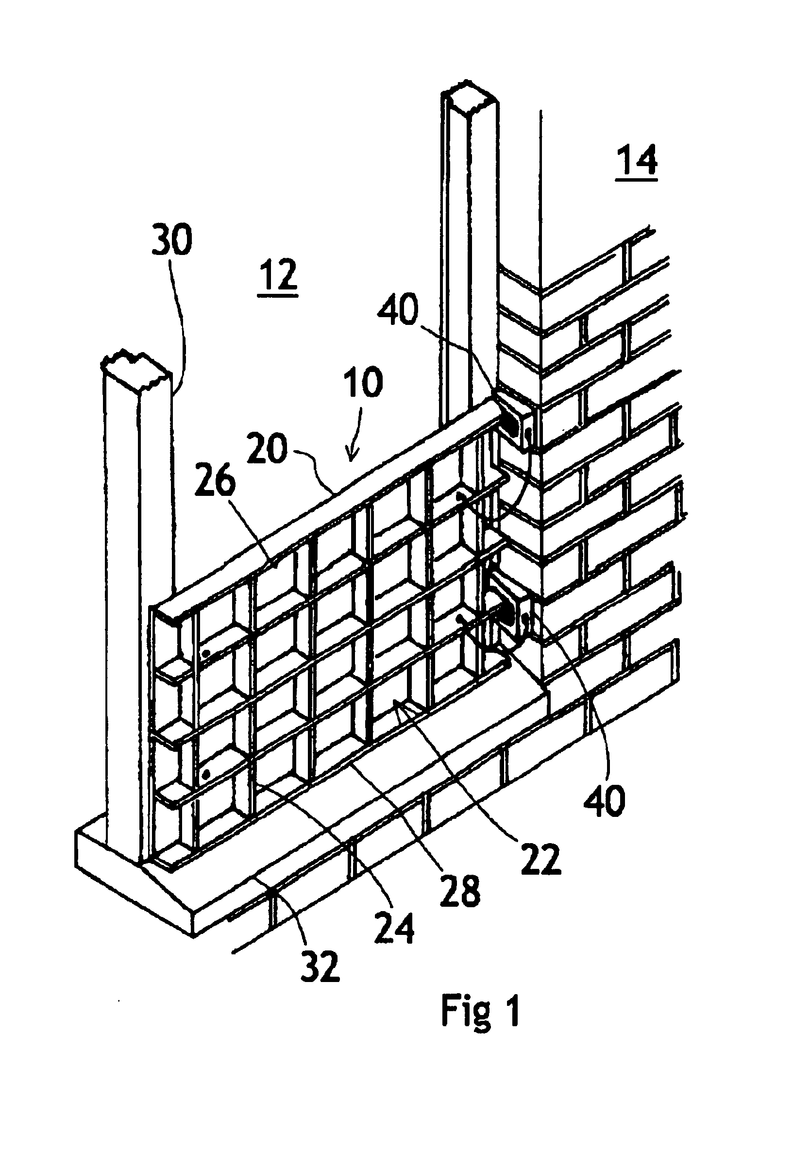
[0024]With reference first to FIG. 1, there is shown a flood protection barrier 10 being a first embodiment of the invention. This embodiment is intended to resist floodwater entering a building through a door aperture 12 formed in a wall 14 of the building.

[0025]The barrier 10 includes a shield 20. The shield 20 includes a generally rectangular plate member 22 formed of a stiff, water-resistant material such as a tough polymer, a composite (e.g. glass-reinforced plastic) or suitably treated timber sheet.

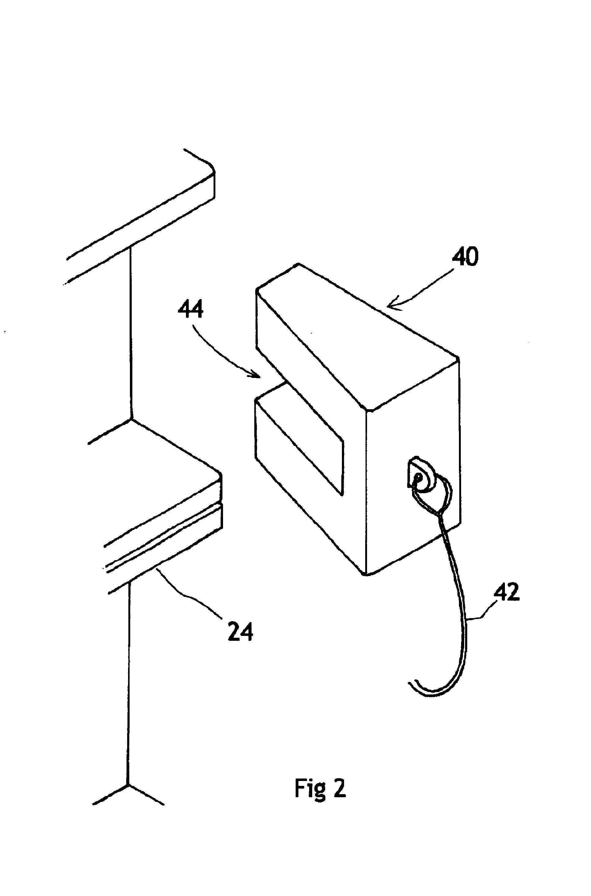
[0026]One side of the plate member 22 (disposed to face into the door aperture, as shown in FIG. 1) is generally flat, and carries sealing elements, to be described below. The opposite side of the plate member (disposed to face out from the door aperture, as shown in FIG. 1) is formed with a plurality of strengthening ribs 24, arranged, in this embodiment, in a grid disposition. As will be understood, strengthening may be included on the plate member 22 as required to impart the shi...


PUM


Abstract

A flood protection barrier is disclosed that can be deployed in the event of an immanent flood risk. The barrier comprises a shield having a sealing element and securing means for securing the shield in place to at least partially close an aperture in a wall of a building. The sealing element forms a fluid-resistant seal between barrier and the periphery of the aperture thereby resisting passage of water through the aperture. The barrier can be secured by securing means that require no modification to the building. The securing means may include clip assemblies or, in alternative embodiments, wedges or other suitable components.

Description

[0001]This is a continuation-in-part of International Application PCT / GB01 / 04897, with an international filing date of Nov. 2, 2001, published in English under PCT Article 21(2) as International Publication Number WO 02 / 40818 A1.BACKGROUND TO THE INVENTION[0002]1. Field of the Invention[0003]This invention relates to a flood protection barrier. In particular, it relates to a flood protection barrier that can be installed to protect premises from an imminent flood risk.[0004]As is well known, rising floodwater can cause extensive damage to the fabric and content of a building with alarming rapidity. Heavy rain and / or high tides can cause rivers to burst their banks and inundate a large area.[0005]Traditionally, there has been little contingency action available to premises owners other than building a defensive barrier of sand bags. Sand bags can act as a reasonably effective filter to remove mud from floodwater. However, these are inconvenient, require a large amount of time and lab...

Claims


Application Information

Patent Timeline
IPC IPC(8): E06B9/00E05B65/04
CPCE06B9/00E06B2009/007
Inventor JONES, ROBERT ALEXANDERJONES, PETER ANTHONY
Owner HELHOLT FLOOD LTD
Learn More