
Smart methane monitor

Active Publication Date: 2011-10-13
HEATH CONSULTANTS
View PDF13 Cites 83 Cited by
  • Summary
  • Abstract
  • Description
  • Claims
  • Application Information

AI Technical Summary

Benefits of technology

[0015]Another object of the invention is to provide a methane detector that uses Smart Energy™ communication networks for compatibility, rapid deployment, and low cost.

Problems solved by technology

Routine periodic leak surveys are costly, and it is estimated that the natural gas distribution and transmission industry spends over $300 million annually to survey the pipeline network for leaks.
Moreover, because gas leaks may occur at appliances or within interior distribution piping on the consumer side of the gas meter, utility pipeline surveys are of limited effect.
Gas explosions due to leakage and accumulation of natural gas in end-user buildings are an unfortunate and too frequent occurrence.
CGIs are low-sensitivity devices that are generally unable to detect gas mixtures much below the lower combustible concentration limit.
However, CGIs, FIDs, OMDs, and laser detectors are generally considered to be too expensive to be widely accepted for home use and thus find limited use, typically in potentially hazardous industrial locations.
These sensors are inexpensive, but they have significant performance limitations.
Electrochemical catalytic semiconductors are unstable, prone to drift, and subject to false alarms due to moisture or household chemicals.
The sensors, which are easily contaminated by household chemicals, have a relatively short life span.
Additionally, there is no practical way for the home owner to test the calibration and functioning of the detector.
As a result, the homeowner is at risk that the methane sensor may frequently trigger false alarms or may not alarm at all when a detectable hazardous condition is present.
Although state and federal safety commissions are increasingly urging the use of natural gas monitors, there is currently little utility company monitoring of detectable atmospheric gas levels at the end-user locations.
Low cost electrochemical semiconductor methane sensors are too prone to false alarms, and more reliable detectors have been too expensive to deploy.
Perhaps a more significant barrier has been the lack of a low cost reliable infrastructure through which a multitude of methane detectors can communicate back to the utility company.

Method used


Image

  • Smart methane monitor
  • Smart methane monitor
  • Smart methane monitor

Examples


Embodiment Construction

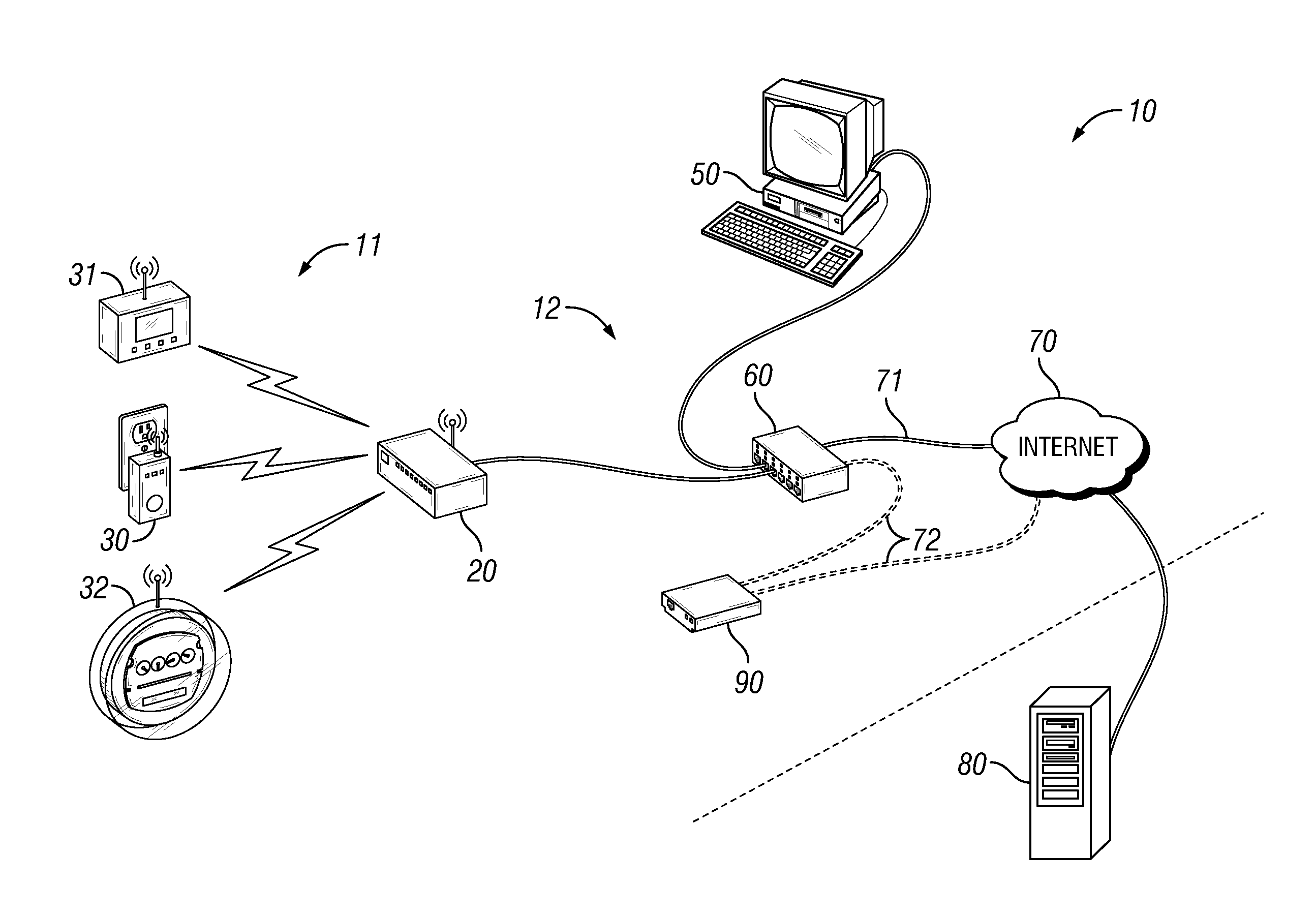
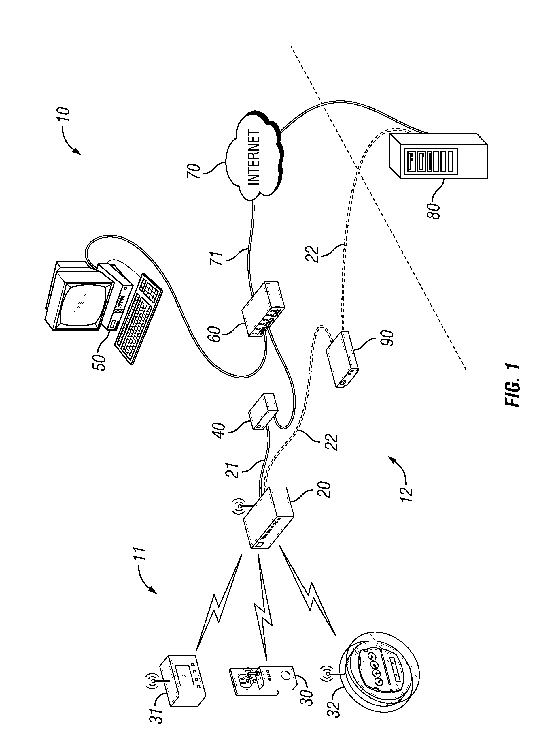
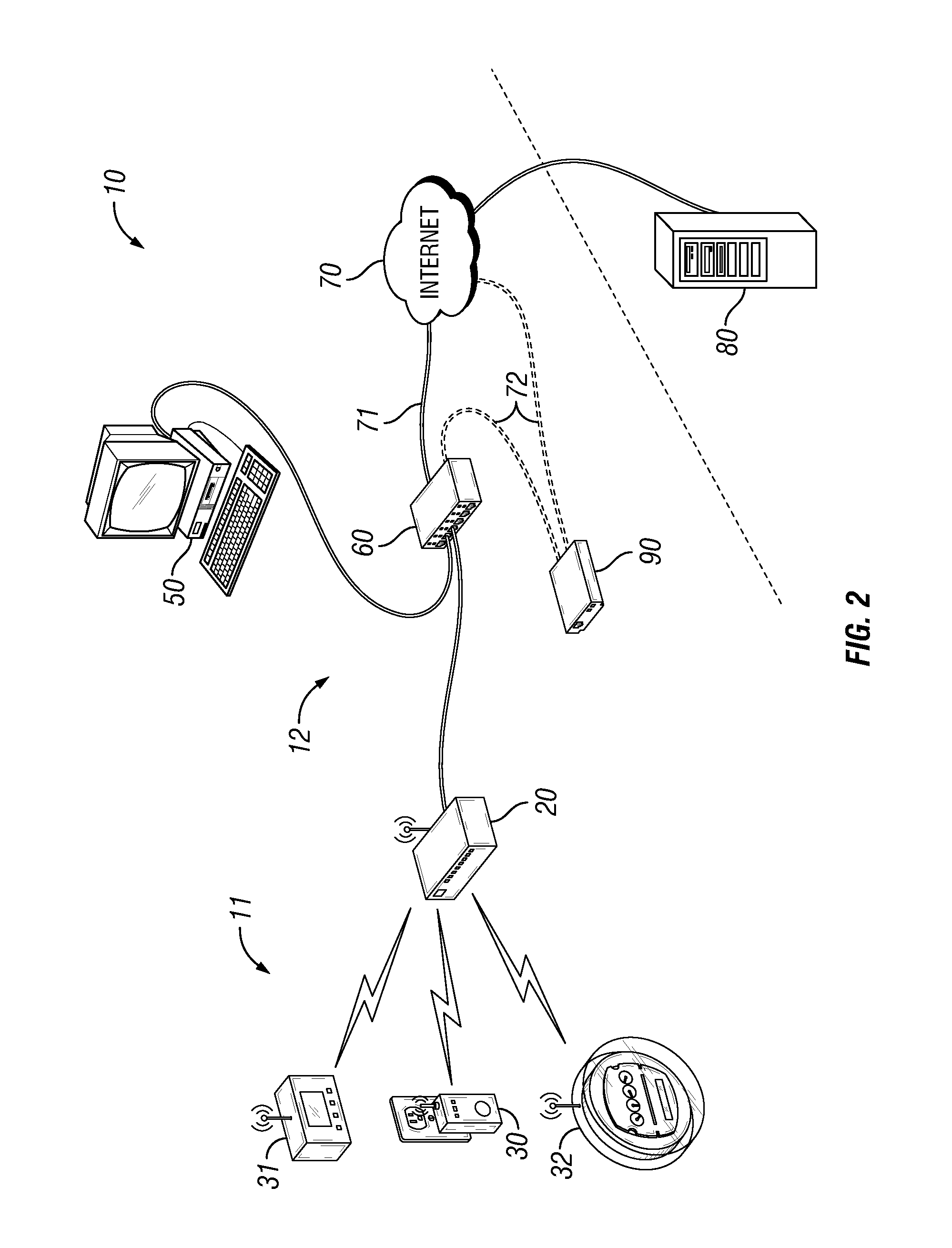
[0033]FIGS. 1-3 illustrate exemplar “Smart Energy™” or “Smart Grid” networks 10 according to a preferred embodiment of the invention. “Smart Energy” is a relatively new and rapidly developing technology being embraced by a number of utility companies. Smart energy offers utility companies secure, easy-to-use wireless home area networks (HAN) for implementing energy management programs under anticipated government mandates to control or ration the distribution of energy. Smart energy allows utilities to directly communicate with smart meters, thermostats, load control devices, and other smart appliances of end users. Advanced metering is available for multiple energy commodities including electricity, natural gas and water. Advanced metering, which allows multiple measurement types such load profile, power factor, summation, demand and tiers, can provide real-time consumption information to both the consumer and the utility. Demand response and load control is a smart energy techniqu...


PUM


Abstract

A method and apparatus for the detection of methane gas including a low-cost low-power infrared methane sensor integrated with a smart energy network endpoint node, a volume corrector, or an electronic data recorder for transmission of alarm conditions and detector data between the instrument and a remote gas utility company. An independent gas calibration / verification cell may be included in the methane detector for periodically testing the functioning and calibration of the infrared sensor. An infrared carbon monoxide sensor and associated calibration / verification cell may also be installed with the methane sensor.

Description

BACKGROUND OF THE INVENTION[0001]1. Field of the Invention[0002]This invention relates generally to remote monitoring systems, and in particular to remote methane monitoring systems for the purpose of detecting the presence of natural gas leaks within residential, commercial, and industrial facilities.[0003]2. Background Art[0004]Natural gas utility companies operate approximately 61 million customer gas meters in the United States alone, supplied by over one million miles of pipeline, 17 hundred transmission stations and 17 thousand compressors. To help maintain security and integrity of this vast distribution system, the natural gas utility industry installs volume correctors and electronic data recorders at compressor stations, metering stations, step-down stations and meter vaults, for example, which provide trend data about the functionality of the distribution system. A volume corrector is typically installed with a gas meter. The volume corrector accurately measures the press...

Claims


Application Information

Patent Timeline
IPC IPC(8): G08B17/10
CPCG08B25/10G08B21/16Y02B70/34Y04S20/30G01D4/002H04Q9/00
Inventor RUTHERFORD, JAMESWEHNERT, PAULCHANCEY, STEVE
Owner HEATH CONSULTANTS
Learn More