
Antenna diversity receiver

Inactive Publication Date: 2005-08-16
CONTINENTAL AUTOMOTIVE GMBH
View PDF26 Cites 20 Cited by
  • Summary
  • Abstract
  • Description
  • Claims
  • Application Information

AI Technical Summary

Benefits of technology

[0008]In a receiver with dynamic IF selectivity, the IF bandwidth is variable, therewith causing the delay to vary as well such that the smaller the IF bandwidth the longer the delay and vice versa. However, the longer the delay, the greater the risk of oscillating false antenna switching actions. By introducing the delay as a new parameter for disabling antenna switching actions in accordance with the invention, any antenna switching action is disabled when and for the time the delay exceeds the predetermined critical value. This allows for a combination of the features of antenna diversity and dynamic IF selectivity, while preventing antenna switching actions from oscillating.
[0009]Preferably, the antenna diversity receiver is characterized by an adjacent channel detector coupled to a bandwidth variable intermediate frequency (IF) circuit. The predetermined critical signal delay value defines a critical bandwidth for the bandwidth variable IF circuit. The switching means is automatically disabled when the bandwidth of the bandwidth variable IF circuit is smaller than the critical bandwidth. This measure is based on the above mentioned correspondence between the IF bandwidth and the delay between the actual occurrence of a multipath caused signal dip and the detection of it. The bandwidth of the bandwidth variable intermediate frequency (IF) circuit is accurately reflected in the output signal of the adjacent channel detector. This allows for a simple implementation of the invention.
[0011]With a simple adjustment of the threshold voltage, the critical bandwidth can be set at a value preventing the antenna switching actions from oscillating and providing an effective adjacent channel suppression on the other hand. An antenna diversity receiver, which is provided with a fixed timer circuit introducing a fixed switching disabling period following each antenna switching action in accordance with the invention is preferably characterized by the bandwidth variable intermediate frequency (IF) circuit effecting a signal delay at the critical bandwidth corresponding to the fixed switching disabling period.
[0012]Such a fixed timer circuit is included in the Philips' TEA 6101 antenna diversity integrated circuit and may well be combined with the antenna switching disabling functionality initiated by the above switching disabling control signal. The use of the fixed switching disabling period as a reference for the determination of the critical bandwidth avoids the occurrence of antenna switching oscillations throughout the complete bandwidth control range of the bandwidth variable intermediate frequency (IF) circuit.
[0014]Another preferred embodiment of antenna diversity receiver provides for a simple combination of both the adjacent channel suppression feature with the antenna diversity feature is characterized in providing the adjacent channel detector with a multiplex input coupled to an output of the demodulator for detecting adjacent channel reception at the occurrence of both an amplitude variation in the IF signal level as well as distortion components in the demodulator output signal.

Problems solved by technology

However, the longer the delay, the greater the risk of oscillating false antenna switching actions.

Method used


Image

  • Antenna diversity receiver
  • Antenna diversity receiver

Examples


Embodiment Construction

[0018]While the present invention is capable of embodiment in various forms, there is shown in the drawings and will hereinafter be described a presently preferred embodiment with the understanding that the present disclosure is to be considered as an exemplification of the invention, and is not intended to limit the invention to the specific embodiment illustrated.

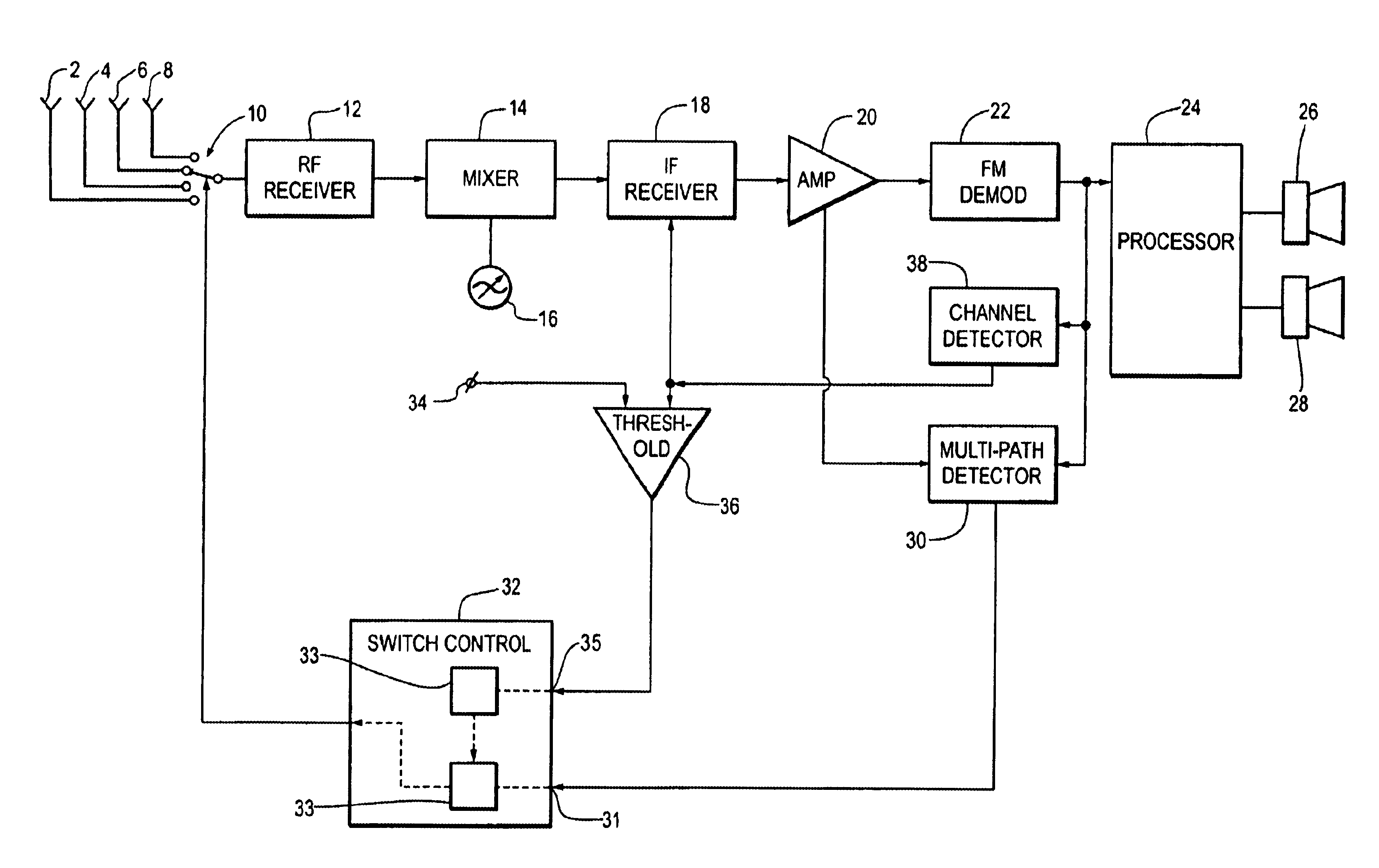
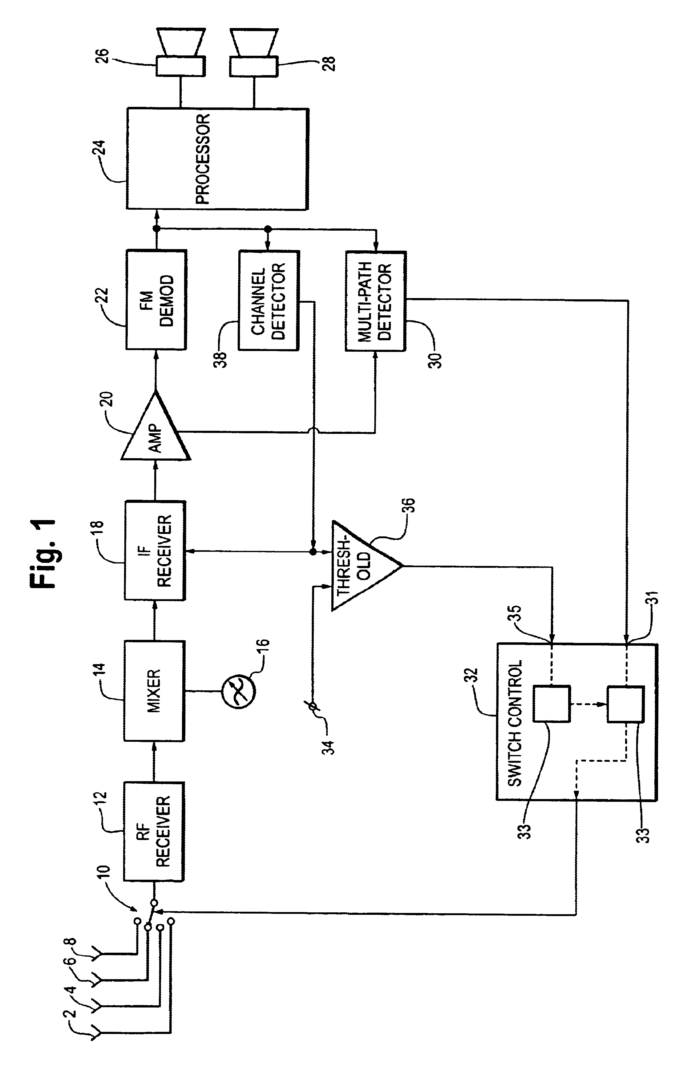
[0019]FIG. 1 shows an antenna diversity FM receiver having first to fourth antennas 2, 4, 6 and 8 coupled through an antenna selective switching circuit 10 to a RF receiver input circuit 12. The RF receiver input circuit 12 is followed by a mixer device 14 which is supplied with a tunable local oscillator signal from an oscillator circuit 16, a variable bandwidth intermediate frequency (IF) selector circuit 18 (selective IF circuit), a IF amplifier 20, an FM demodulator 22 and a baseband modulation signal processor 24. The baseband modulation signal processor 24 is coupled to stereo left and stereo right signal reproducin...


PUM


Abstract

An antenna diversity receiver is disclosed. The diversity receiver has a multipath detector for controlling an antenna selective switching circuit. The switching circuit couples one of a plurality of antennas to a RF receiver input. The receiver allows suppression of adjacent channel interferences without unwanted side effects by employing a switching disabling circuit to automatically disabling the switching circuit when the signal delay between the occurrence of multipath distortions in the RF reception signal and the switching between antennas exceeds a predetermined critical signal delay value.

Description

FIELD OF INVENTION[0001]This invention relates to an antenna diversity receiver which has a selective switching circuit for coupling one of a plurality of antennas to a RF receiver input, as well as a multipath detector for controlling the selective switching circuit.BACKGROUND OF INVENTION[0002]The reception of a wanted RF broadcast transmitter signal may be disturbed or otherwise deteriorated by various phenomena, such as multipath reception and / or adjacent channel interferences. In general, multipath reception is caused by signal reflections at and / or against environmental physical obstacles such as mountains, trees, buildings, fences and the like. Due to such signal reflections a RF broadcast signal may arrive at a certain reception location through various different signal paths which result in different amplitude and phase conditions. The summation of these multipath signals at the antenna of the receiver results in unpredictable signal amplitude and / or phase distortions. Thes...

Claims


Application Information

Patent Timeline
IPC IPC(8): H04B7/08H01Q3/24
CPCH04B7/0805
Inventor MEIJER, PIETERTOFFOLO, FRANCOBANZIGER, CHRISTIAAN MARIE HUBERTUS
Owner CONTINENTAL AUTOMOTIVE GMBH
Learn More