
Generating electronic carrier signals in the optical domain

a technology of electronic carrier signals and optical domains, applied in the direction of optical resonator shape and construction, electromagnetic transmission, transmission, etc., can solve the problem and achieve the effect of narrow optical linewidth

Inactive Publication Date: 2005-08-16
ASTON UNIV
View PDF5 Cites 9 Cited by
  • Summary
  • Abstract
  • Description
  • Claims
  • Application Information

AI Technical Summary

Benefits of technology

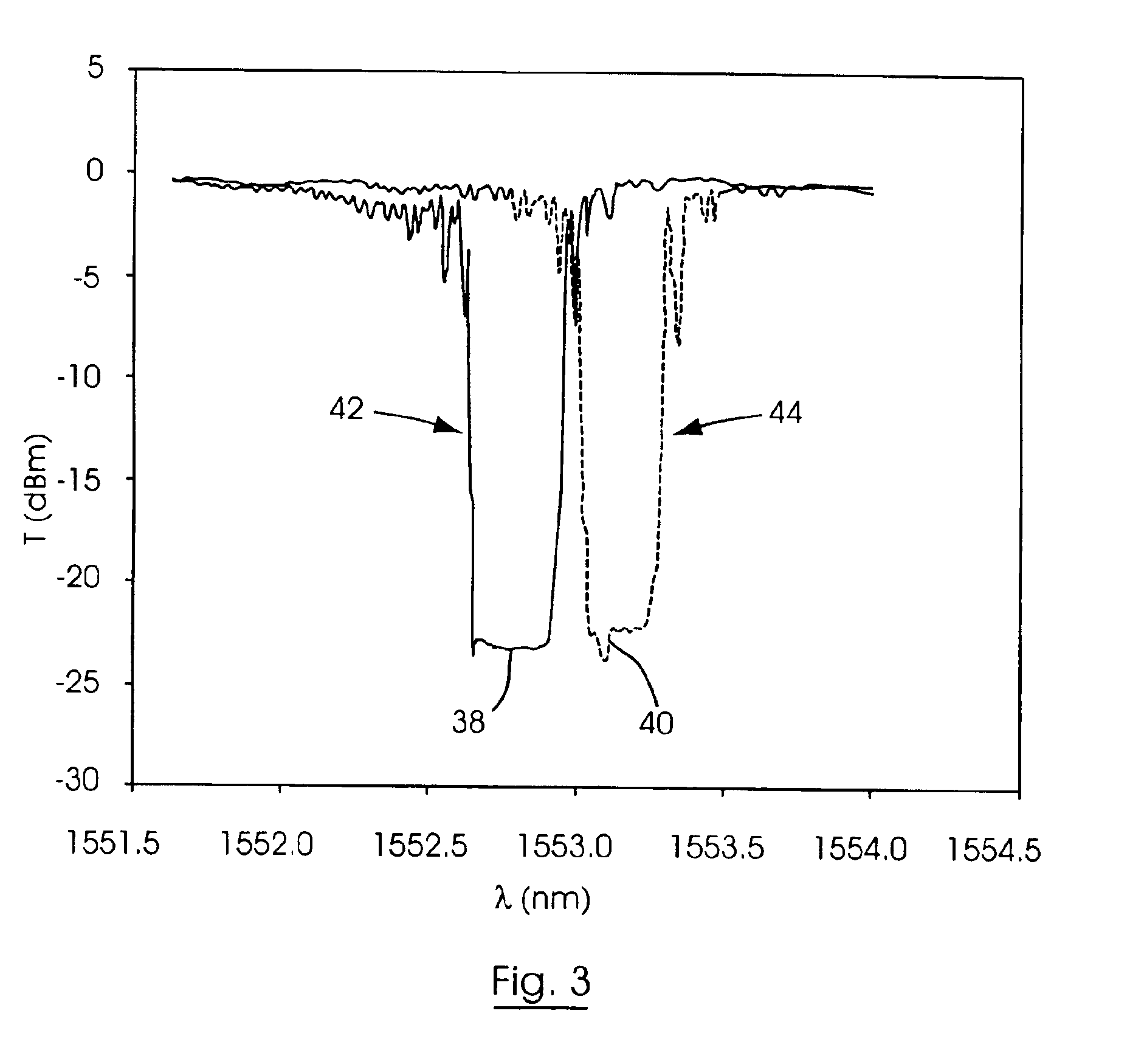
[0008]There remains a need, therefore, for a photonic source that can generate an optical output at two closely spaced wavelengths, having a narrow intrinsic optical linewidth. In one approach according to the present invention, a waveguide laser is capable of lasing at two different modes, in each of two different orthogonal polarization states, giving a total of four different potential lasing modes. The selection of a pair of orthogonally polarized modes results in the laser operating at two orthogonally polarized lasing modes, at two closely spaced wavelengths, without suffering mode competition within the laser cavity. Since the two lasing modes oscillate within substantially the same optical cavity, both modes have the same phase noise, resulting in a narrow optical linewidth.
[0020]The polarization mode-coupling optical waveguide grating may be coupled to a wavelength tuning-device operable to change the birefringence of the second grating section, thereby changing the resonant wavelength of one or both of the reflection peaks of the grating, thus enabling a user to select at which pair of orthogonally polarized, potential lasing modes the laser will operate.

Problems solved by technology

Since the two lasing modes oscillate within substantially the same optical cavity, both modes have the same phase noise, resulting in a narrow optical linewidth.

Method used


Image

  • Generating electronic carrier signals in the optical domain
  • Generating electronic carrier signals in the optical domain
  • Generating electronic carrier signals in the optical domain

Examples


Embodiment Construction

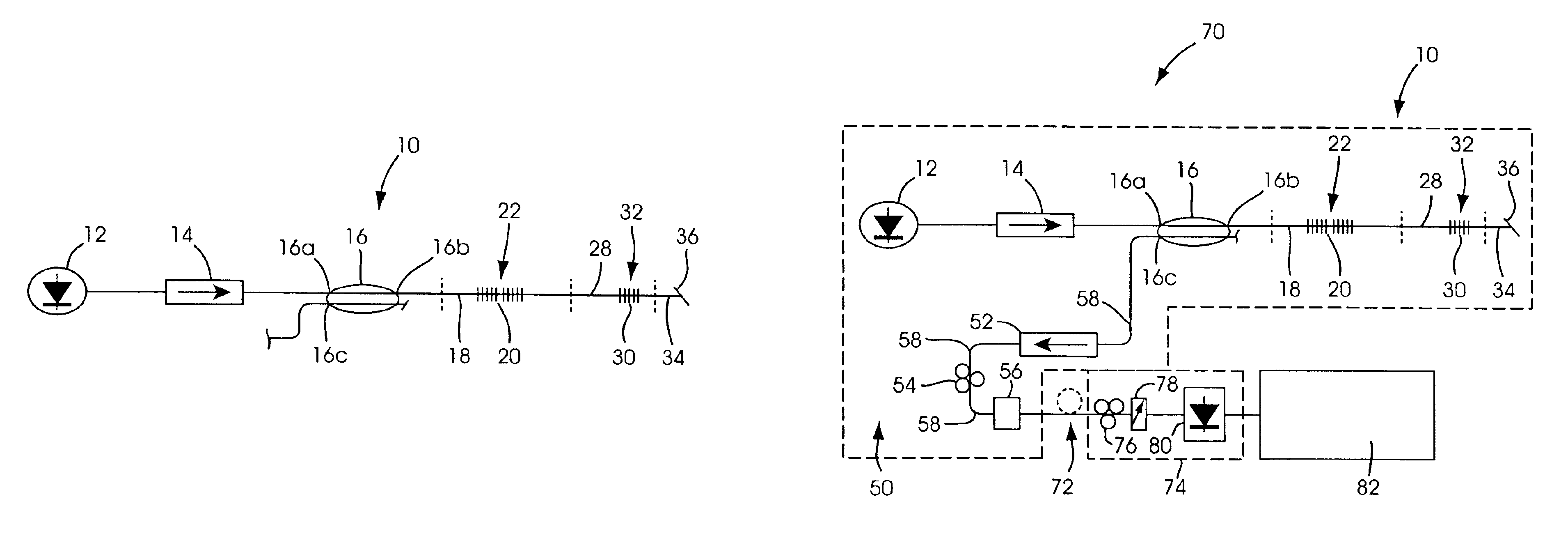
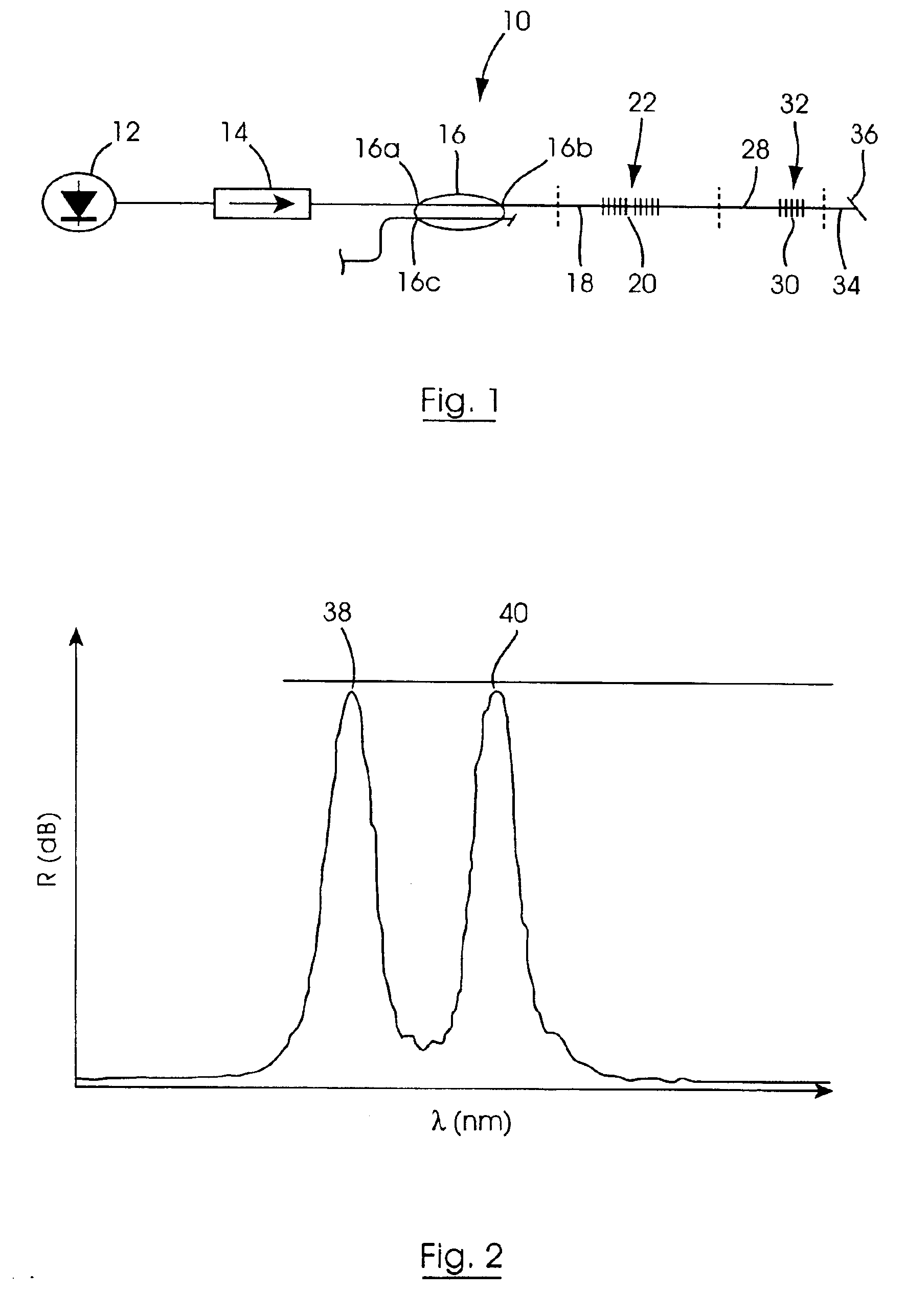
[0045]Referring to FIGS. 1-8 of the drawings, one particular embodiment of the invention is directed to a dual wavelength optical waveguide laser, which in this example takes the form of a dual wavelength fiber grating distributed feedback (DFB) laser 10, constructed as follows. A pump laser diode 12 is optically coupled, via a 980 nm optical fiber isolator 14, to a first port 16a on one side of a 980 nm / 1550 nm wavelength division multiplexed (WDM) fiber coupler 16. The pump laser diode 12 is operable to generate a laser output signal having a wavelength of 980 nm. The isolator 14 reduces the possibility of any back-reflections from the other components of the laser 10 from disturbing the pump laser 12.

[0046]A first port 16b on the other side of the WDM coupler 16 is coupled to a first optical waveguide, which in this example takes the form of an erbium-ytterbium (Er—Yb) co-doped optical fiber 18. A first optical waveguide grating device 20, which in this example comprises two co-l...


PUM


Abstract

A dual wavelength optical fiber distributed feedback laser comprises a pump laser coupled to a birefringent fiber in which a first grating device (two co-located single phase-shift fiber Bragg gratings (FBGs)) is provided. The grating device gives the laser two potential lasing modes in each of two orthogonal polarization states. A polarization mode coupling FBG selects two orthogonally polarized modes on which the laser oscillates. In a photonic data carrying signal source, the laser is coupled to a polarization dependent, optical modulator operable to apply a modulation, at a data signal frequency, to one polarization mode of the laser output. In an optical waveguide based electronic signal transmission system the modulated and un-modulated polarization modes output from the source are transmitted across a fiber transmission line to a polarizing optical fiber in which the two modes heterodyne to generate an electronic carrier signal in the optical domain.

Description

RELATED APPLICATION[0001]This application claims priority from European Patent Application Ser. No. 02251581.1, filed on Mar. 6, 2002, which is incorporated herein by reference.FIELD OF THE INVENTION[0002]The invention relates to the generation of electronic carrier signals in the optical domain, and specifically to a dual wavelength optical waveguide laser and to photonic data carrying signal generation and transmission.BACKGROUND OF THE INVENTION[0003]Optical fiber microwave systems offer an effective method for delivery of broadband wireless communication services. Optical fiber microwave systems are used in applications such as personal communications networks, millimeter-wave radio local area networks, broadband video distribution networks and signal distribution for phased array antennas. These systems could therefore play an important role in metropolitan area telecommunications networks. A key requirement of optical fiber microwave systems is an efficient technique for the o...

Claims


Application Information

Patent Timeline
Patent Type & Authority Patents(United States)
IPC IPC(8): H01S3/081H01S3/082H01S3/06H01S3/067H01S3/08H01S3/063
CPCH01S3/0675H01S3/082H01S3/063H01S3/0635H01S3/06712H01S3/08086H01S3/0809H01S3/2308
Inventor WILLIAMS, JOHN ARTHUR ROBERTLAI, YICHENGZHANG, WEI
Owner ASTON UNIV
Learn More