
Process for the preparation of diisocyanates

a technology of diisocyanates and triisocyanates, which is applied in the preparation of isocyanic acid derivatives, gas-gas reaction processes, organic chemistry, etc., can solve the problems of reducing the mixing rate of the central jet, and affecting the stability of the reaction process

Active Publication Date: 2005-08-16
COVESTRO DEUTSCHLAND AG
View PDF3 Cites 36 Cited by
  • Summary
  • Abstract
  • Description
  • Claims
  • Application Information

AI Technical Summary

Benefits of technology

The present invention is about a process for making diisocyanates and triisocyanates. The process involves using a tubular reactor with a double-walled guide tube and a concentric annular gap between the inner and outer walls. The process involves gas phase phosgenating the corresponding diamines and / or triamines by heating them in vapor form and phosgene separately. The diamines and / or triamines are fed to the tubular reactor via the concentric annular gap at a high flow velocity, while the phosgene is fed to the tubular reactor at a high flow velocity over the remaining cross-sectional areas of the tubular reactor. The technical effect of this process is to increase the yield and purity of diisocyanates and triisocyanates.

Problems solved by technology

This results in soiling of the reactor below the mixing zone and in blockages of the reactor.
With the increase in the diameter of the smooth jet nozzle, however, the rate of mixing of the central jet is reduced by the greater diffusion distance required and the danger of back-mixing is increased, which in turn leads to the formation of polymeric impurities and hence caking of solid materials in the reactor.

Method used


Image

  • Process for the preparation of diisocyanates
  • Process for the preparation of diisocyanates

Examples


example 1

Example According to the Invention

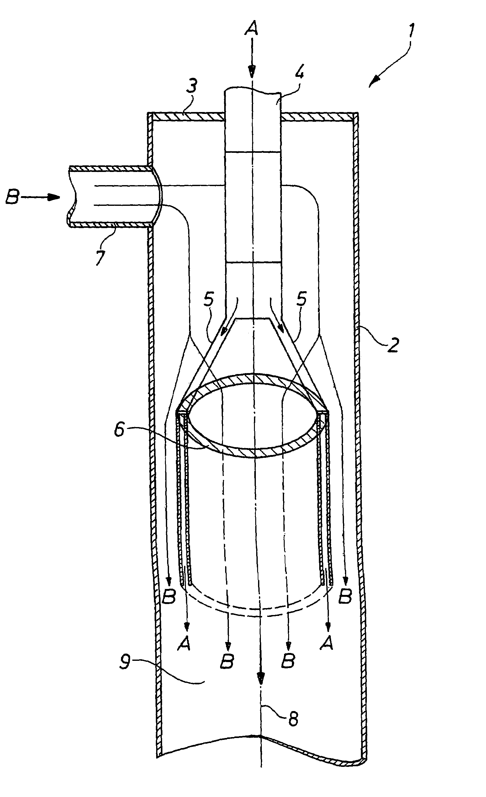
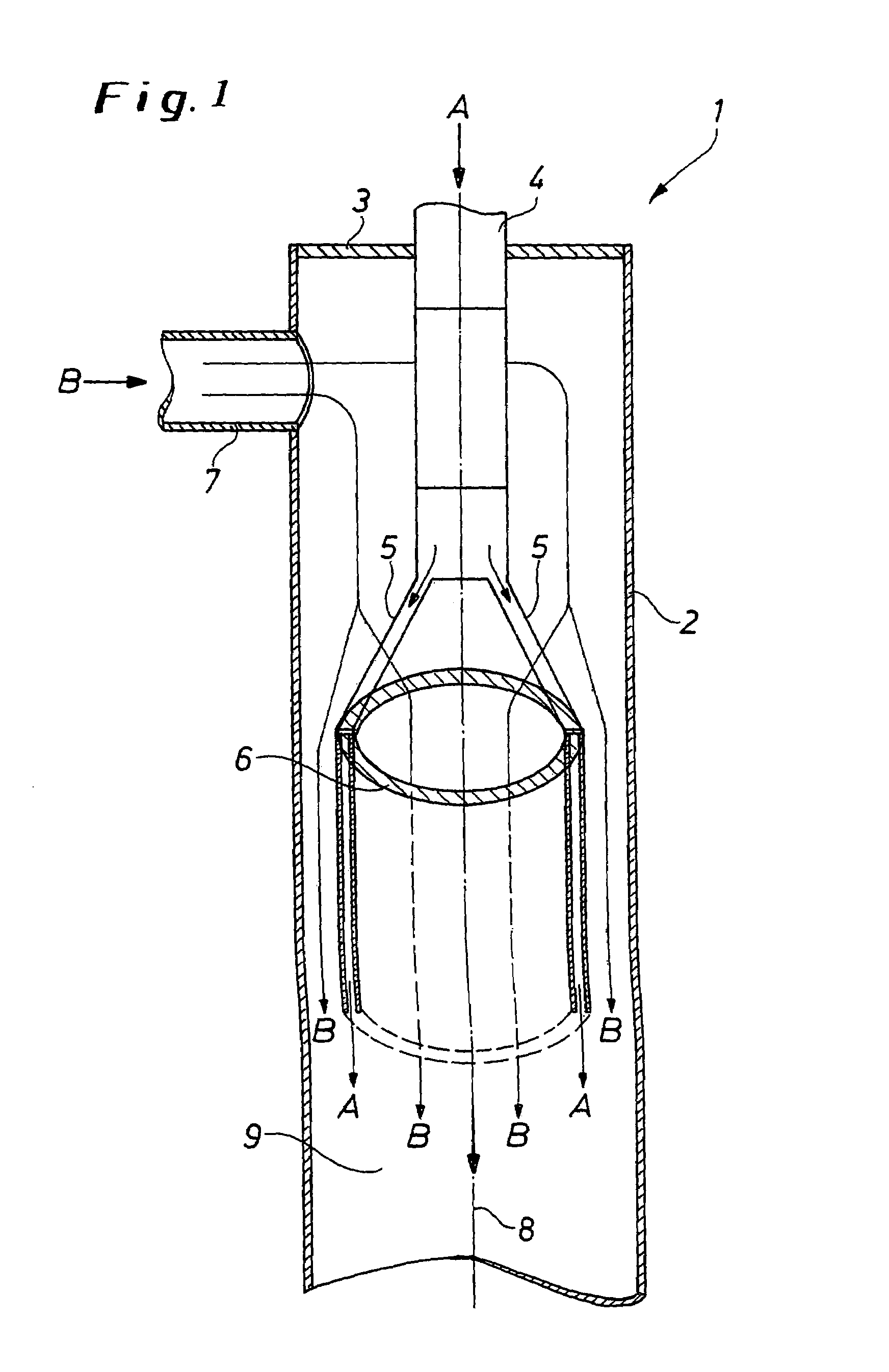
[0043]An isophoronediamine / inert gas mixture, as starting material stream A, and phosgene as starting material stream B are passed continuously into a tubular reactor according to FIG. 1, comprising a downstream isocyanate condensation stage and isocyanate working-up downstream thereof. The temperatures of the two starting material streams are 300° C. The pressure in the tubular reactor is slightly above atmospheric pressure at 1400 mbar.

[0044]The velocity of the component A in the double-walled guide tube 6 is about 60 m / s and that of component B prior to mixing is about 7 m / s. The ratio of the cross-sectional area of the tubular reactor 1, which area is bounded by the inner wall of the double-walled guide tube 6, to the cross-sectional area of the tubular reactor, which area is bounded by the cylindrical wall 2 of the tubular reactor and the outer wall of the double-walled guide tube, is 1:1.

[0045]The velocity of the reaction mixture at the reacto...

example 2

Comparative Example

[0047]Example 1 is repeated under the same conditions, a smooth jet nozzle being used instead of the double-walled guide tube. The cross-sectional flow areas for the isophoronediamine / inert gas mixture and phosgene at the exit from the nozzle are equal to the cross-sectional flow areas in the tubular reactor according to example 1.

[0048]It is found that, with the use of the conventional smooth jet nozzle at comparable velocities of the components at the mixing point, the maximum temperature in the tubular reactor is reached only substantially later, namely only about five diameters of the cylindrical wall 2 away from the mixing point in the downstream direction. The yield of IPDI, based on the IPDA used, is 98.5% of theory.

[0049]In addition, it is found that the formation of polymeric byproducts which are deposited on the wall of the tubular reactor is reduced by the better and faster mixing with the use, according to the invention, of the tubular reactor having a...


PUM

PropertyMeasurementUnit
temperaturesaaaaaaaaaa
mean flow velocityaaaaaaaaaa

Abstract

The invention relates to a process for the preparation of isocyanates in the gas phase, in which the possibilities for back-mixing and byproduct formation are reduced by improving the mixing of the starting materials in a tubular reactor.

Description

CROSS REFERENCE TO RELATED PATENT APPLICATION[0001]The present patent application claims the right of priority under 35 U.S.C. § 119 (a)–(d) of German Patent Application No.103 59 627.5, filed Dec. 18, 2003.BACKGROUND OF THE INVENTION[0002]1. Field of the Invention[0003]The present invention relates to a process for the preparation of diisocyanates and / or triisocyanates by phosgenation of the corresponding diamines and / or triamines in the gas phase.[0004]2. Description of the Prior Art[0005]The preparation of isocyanates by reaction of amines with phosgene in the gas phase has long been known (cf. Siefken, Annalen 562, 108 (1949). Gas-phase reactions can be carried out in various ways. Nozzles, burners or mixing tubes are used for mixing the starting materials. For the gas-phase phosgenation of diisocyanates, the use of nozzles has been very generally described. These are, as described, for example, in EP-A1-0593334, smooth jet nozzles or concentric feed tubes. Usually, one of the s...

Claims


Application Information

Patent Timeline
Patent Type & Authority Patents(United States)
IPC IPC(8): C07C263/00C07C263/10C07C265/14C07C265/00C07C265/04C07C265/10
CPCC07C263/10C07C265/14B01J4/001B01J12/00B01J19/0053B01J19/1843B01J19/2415B01J4/002B01J4/005B01J2219/00164B01J19/244Y02P20/141
Inventor MEYN, JURGENSTUTZ, HERBERT
Owner COVESTRO DEUTSCHLAND AG
Learn More