
Method for aluminide coating of gas turbine engine blade

a gas turbine engine and aluminide coating technology, which is applied in the direction of solid-state diffusion coating, machines/engines, mechanical equipment, etc., can solve the problems of affecting the performance of the engin

Active Publication Date: 2005-08-16
GENERAL ELECTRIC CO
View PDF30 Cites 22 Cited by
  • Summary
  • Abstract
  • Description
  • Claims
  • Application Information

AI Technical Summary

Benefits of technology

[0013](d) flowing an inert carrier gas into the loaded coating chamber comprising the aluminide coating gas at a gas flow rate of from 0 to about 150 ft.3/hour (from 0 to about 4248 liters/hour) for

Problems solved by technology

The maximum temperature of the combustion gases is usually limited by the materials used to fabricate the turbine blades.
However, if the coating is applied at too great a thickness on regions of the blade operating at lower temperatures, such as the root and shank region, the combination of the increased coating thickness and the abrupt transition within the dovetail may cause cracking in the root portion as higher stresses are induced into the transition area of the dovetail.
Over time, continued operation may lead to a premature failure of the blade within the engine.

Method used


Image

  • Method for aluminide coating of gas turbine engine blade
  • Method for aluminide coating of gas turbine engine blade
  • Method for aluminide coating of gas turbine engine blade

Examples


example 1

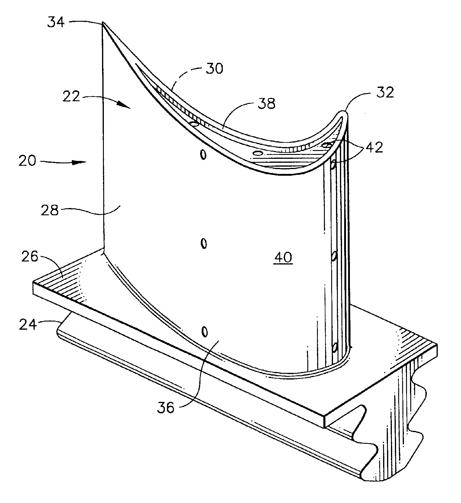
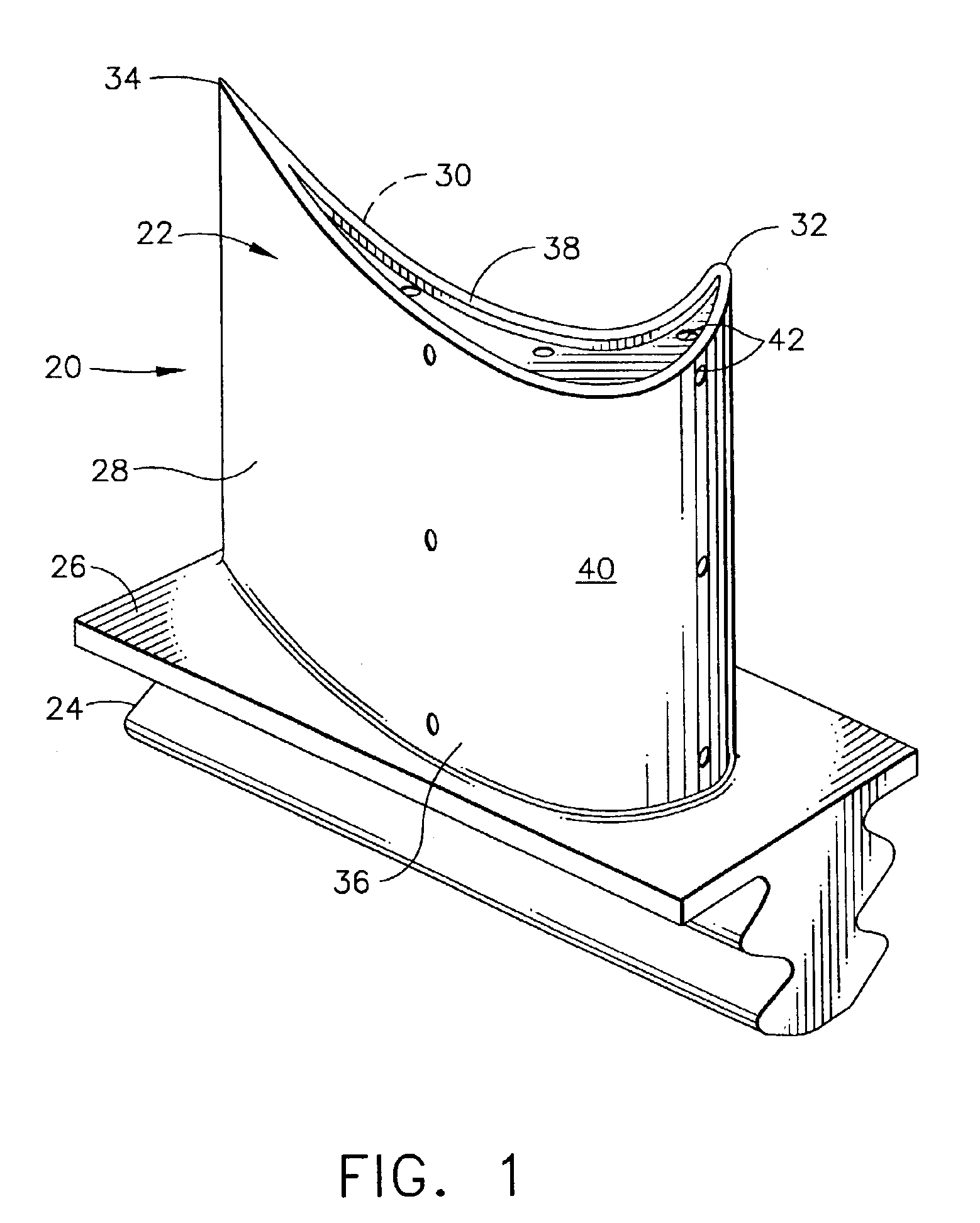
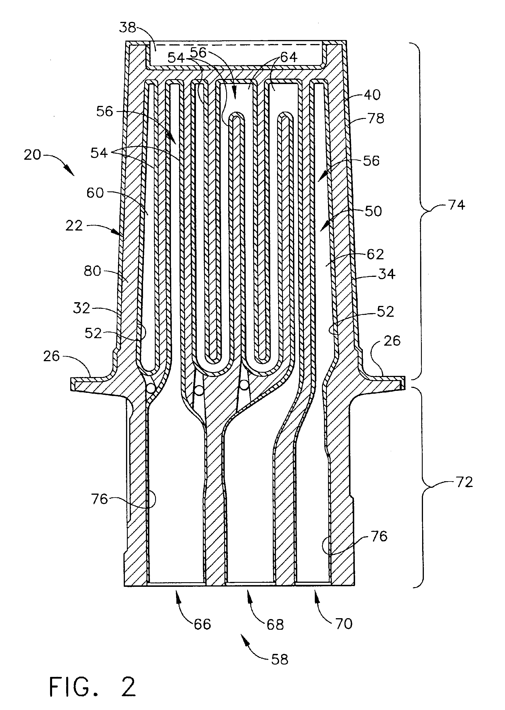
[0045]A two-step process different from the present invention was used to apply an aluminide coating to sample blades in the coating container shown in FIG. 3. In the first step, argon gas was flowed into the coating container to force aluminide coating vapors, formed by reacting aluminum fluoride activator with chromium aluminum alloy pellets as described regarding FIG. 3, to flow through the cooling holes and internal cooling cavities of the blades and out of the dovetail root holes of the blades. In this reverse flow step, an aluminide coating was deposited on internal surfaces of the blades. The thickness of the internal coating and the aluminum content were controlled by the temperature, gas flow, elapsed time of gas flow, and amount of activator in the coating container. In the second step, the argon gas flow to the coating container was stopped, creating a static environment that primarily affected the external portions of the blades and resulted in the deposition of an alumi...

example 2

[0047]Sample blades were coated in the coating container shown in FIG. 3 using a method of the invention. In this method, the coating parameters of Example 1 were altered to deposit a thin, controlled aluminide coating having a thickness of less than 0.0015 inches (about 38.1 microns) on the internal surfaces of all airfoil and dovetail cavities of the blades. In the first step, argon gas was used to flow the aluminide coating vapors through the cooling holes and internal cooling cavities of the blades at a lower temperature. This caused the coating thickness (internal and external) and total aluminum content of the coating to be reduced because of the lower kinetics of diffusion into the substrate. During the second step, the temperature was raised and the gas flow through the internal cooling cavities was reduced to increase the vapor pressure (or activity) of the aluminiding gas and increase the kinetics of aluminum diffusion into the substrate. This resulted in a thicker, higher...


PUM

PropertyMeasurementUnit
Temperatureaaaaaaaaaa

Abstract

A method for applying an aluminide coating on a gas turbine engine blade having an external surface and an internal cooling cavity having an internal surface that is connected to the external surface by cooling holes. The method is conducted in a vapor coating container having a hollow interior coating chamber, and includes the steps of loading the coating chamber with the blade to be coated; providing an aluminide coating gas in the loaded coating chamber; flowing an inert carrier gas into the loaded coating chamber comprising the aluminide coating gas at a specified gas flow rate and time to move the aluminide coating gas through the cooling holes and internal cooling cavity and deposit an aluminide coating on the internal surface of the blade; and then flowing an inert carrier gas into the loaded coating chamber comprising the aluminide coating gas at a specified higher temperature and time to deposit an aluminide coating on the external surface of the blade.

Description

BACKGROUND OF THE INVENTION[0001]The present invention relates to a method for applying a protective coating on a gas turbine engine blade having an internal cooling cavity. More particularly, the invention relates to the aluminide coating of the internal and external surfaces of such a gas turbine blade.[0002]In an aircraft gas turbine engine, air is drawn into the front of the engine, compressed by a shaft-mounted compressor, and mixed with fuel. The mixture is burned, and the hot exhaust gases are passed through a turbine mounted on the same shaft. The flow of combustion gas turns the turbine by impingement against the airfoil section of the turbine blades, which turns the shaft and provides power to the compressor. (As used herein, the term turbine blade may refer to either a turbine blade or a turbine vane, which have similar appearance in pertinent portions.) The hot exhaust gases flow from the back of the engine, driving it and the aircraft forward.[0003]The hotter the combus...

Claims


Application Information

Patent Timeline
IPC IPC(8): C23C10/00C23C10/08F01D5/28C23C16/44
CPCC23C10/08F01D5/288Y02T50/67Y02T50/60
Inventor WUSTMAN, ROGER DALEWALSTON, WILLIAM SCOTTSAYLOR, MATTHEW DAVIDPILSNER, BRIAN HARVEYPFAENDTNER, JEFFREY ALLAN
Owner GENERAL ELECTRIC CO
Learn More