
Method and apparatus for mixing gases

a technology of gas mixing and apparatus, applied in the direction of mixing, transportation and packaging, instruments, etc., can solve the problems of distorting the downstream samples, affecting the quality of gas flow,

Inactive Publication Date: 2005-08-16
CATERPILLAR INC
View PDF21 Cites 202 Cited by
  • Summary
  • Abstract
  • Description
  • Claims
  • Application Information

AI Technical Summary

Problems solved by technology

One problem with placing orifice plates, or other obstructions such as inlet pipes, in the stream is that they tend to collect and remove some of the particulate matter from the stream, which distorts the downstream samples.
Moreover, abrupt changes in tunnel geometry may also cause particulate matter to collect on the tunnel walls.
This particulate matter may build up on the plate or walls over time and then periodically flake off, further distorting the samples taken downstream.
Thus, dilution tunnels for large displacement engines may be very bulky, even taking up entire rooms.
One drawback of this system is that it requires a complex control system for reacting to pressure fluctuations.
Another drawback is that it also requires a complex system of piping, both for splitting the exhaust gas stream and for introducing the pressurized dilution air.
A further drawback is that the exhaust inlet pipe is exposed to the dilution air stream prior to the exhaust gas exiting the inlet pipe, causing undesirable cooling of the exhaust gas prior to mixing.

Method used


Image

  • Method and apparatus for mixing gases
  • Method and apparatus for mixing gases
  • Method and apparatus for mixing gases

Examples


Embodiment Construction

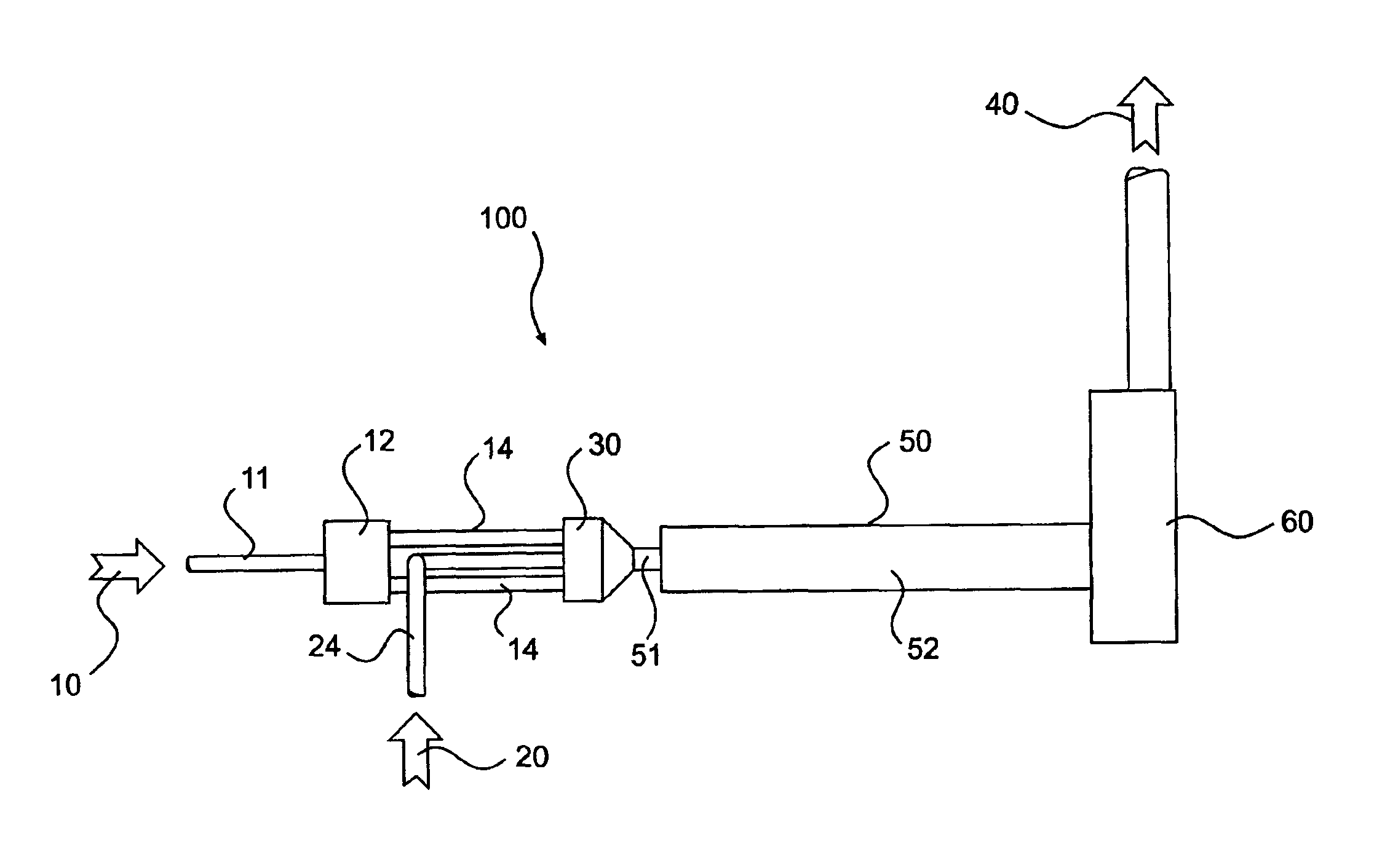
[0017]FIG. 1 shows an apparatus, designated generally by reference number 100, which includes a mixing chamber 30 receiving a first stream 10 and a second stream 20. In one embodiment, first stream 10 may be either a stream of exhaust gas or a stream of dilution gas, and second stream 20 may be the other of the stream of exhaust gas or dilution gas. For example, first stream 10 may be a stream of dilution gas and second stream 20 may be a stream of exhaust gas. Thus, mixing chamber 30, which receives both first stream 10 and second stream 20, would receive, in this embodiment, both the stream of exhaust gas and the stream of dilution gas. The stream of exhaust gas, which may be generated by an engine, such as a diesel engine, contains particulate matter and / or other emissions that are to be measured. The stream of dilution gas may be conditioned air, i.e., air that is filtered, heated, cooled, humidified, de-humidified, etc.

[0018]In one embodiment, as shown in FIG. 1, apparatus 100 ...


PUM

PropertyMeasurementUnit
diameteraaaaaaaaaa
diameteraaaaaaaaaa
lengthaaaaaaaaaa

Abstract

A method and apparatus for mixing a first stream of gas with a second stream of gas is provided. The method includes introducing a first stream of gas into a first stream manifold and directing the first stream from the first stream manifold into a mixing chamber via a plurality of first stream passages flow coupled to the mixing chamber. A second stream of gas is directed into the mixing chamber via at least one second stream passage flow coupled to a first end of the mixing chamber. A combined stream is formed from the first and second streams, gradually converged, and discharged from the mixing chamber through a mixing chamber exit port.

Description

[0001]This application is a divisional of U.S. application Ser. No. 10 / 137,370, filed May 3, 2002, now U.S. Pat. No. 6,684,719, issued on Feb. 3, 2004.TECHNICAL FIELD[0002]The present invention is directed to a method and an apparatus for mixing streams of gases to form a combined stream.BACKGROUND[0003]The federal government and other authorities regulate allowable exhaust emissions from gasoline and diesel engines for automobiles, trucks, and other vehicles, such as off-road construction or agricultural vehicles, in an effort to reduce pollution. In order to ensure compliance with these regulations, the exhaust gases of these engines must be tested or otherwise analyzed for undesirable combustion by-products, such as hydrocarbons, carbon monoxides, sulphates, and / or oxides of nitrogen. In general, testing is accomplished by introducing exhaust gases, diluting these exhaust gases with clean air, and obtaining samples after the exhaust gases and dilution air are properly mixed.[0004...

Claims


Application Information

Patent Timeline
Patent Type & Authority Patents(United States)
IPC IPC(8): B01F3/00B01F3/02B01F5/06B01F5/04G01N1/22B01F23/10G01M15/04
CPCB01F3/02B01F5/045B01F5/0475B01F5/0644G01N1/2252G01N2001/2264Y10T137/87652B01F23/10B01F25/3142B01F25/313B01F25/4323
Inventor GEHNER, GERRICK S.GRAZE, JR., RUSSEL R.IYER, KARTIK G.KOCH, KORBY A.MALLAMPALLI, HEMANT P.WAGNER, JOHN E.
Owner CATERPILLAR INC
Learn More