
Method of monitoring dual-phase liquid and interface levels

Inactive Publication Date: 2005-08-16
ROBBINS BRYCE V
View PDF12 Cites 39 Cited by
  • Summary
  • Abstract
  • Description
  • Claims
  • Application Information

AI Technical Summary

Benefits of technology

[0017]An advantage of the present invention is that it can be removed from an installation for servicing.

Problems solved by technology

While fairly accurate, manually taking the measurements does not provide continuous monitoring, and is time consuming and tedious.
The use of a dedicated detector does avoid cross contamination from the probe, however, the affixing of the detector at a given location limits the versatility of the device.
This drawback is particularly limiting in applications in which multiple locations need to be tested, such as in field pilot-testing.
Moreover, the inability to remove the device from the well makes service on the device difficult if not impossible.
While this method is useful for measurements taken in tanks, the mechanical linkage of the two floats makes the system impractical for deep-well applications.
The requirement for an optical reader also makes the Zinsmeyer method difficult to implement for in-well or on-well applications.

Method used


Image

  • Method of monitoring dual-phase liquid and interface levels
  • Method of monitoring dual-phase liquid and interface levels
  • Method of monitoring dual-phase liquid and interface levels

Examples


Embodiment Construction

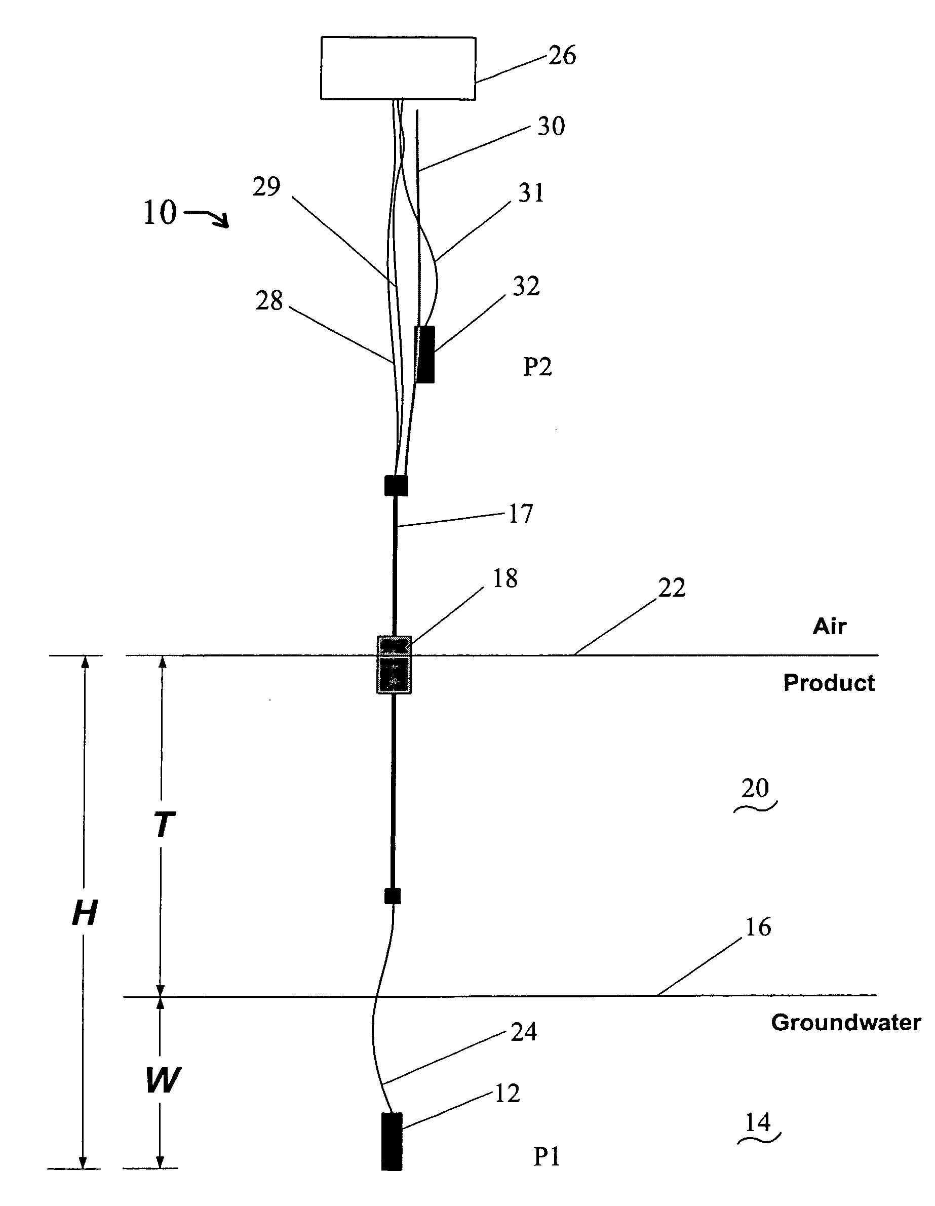
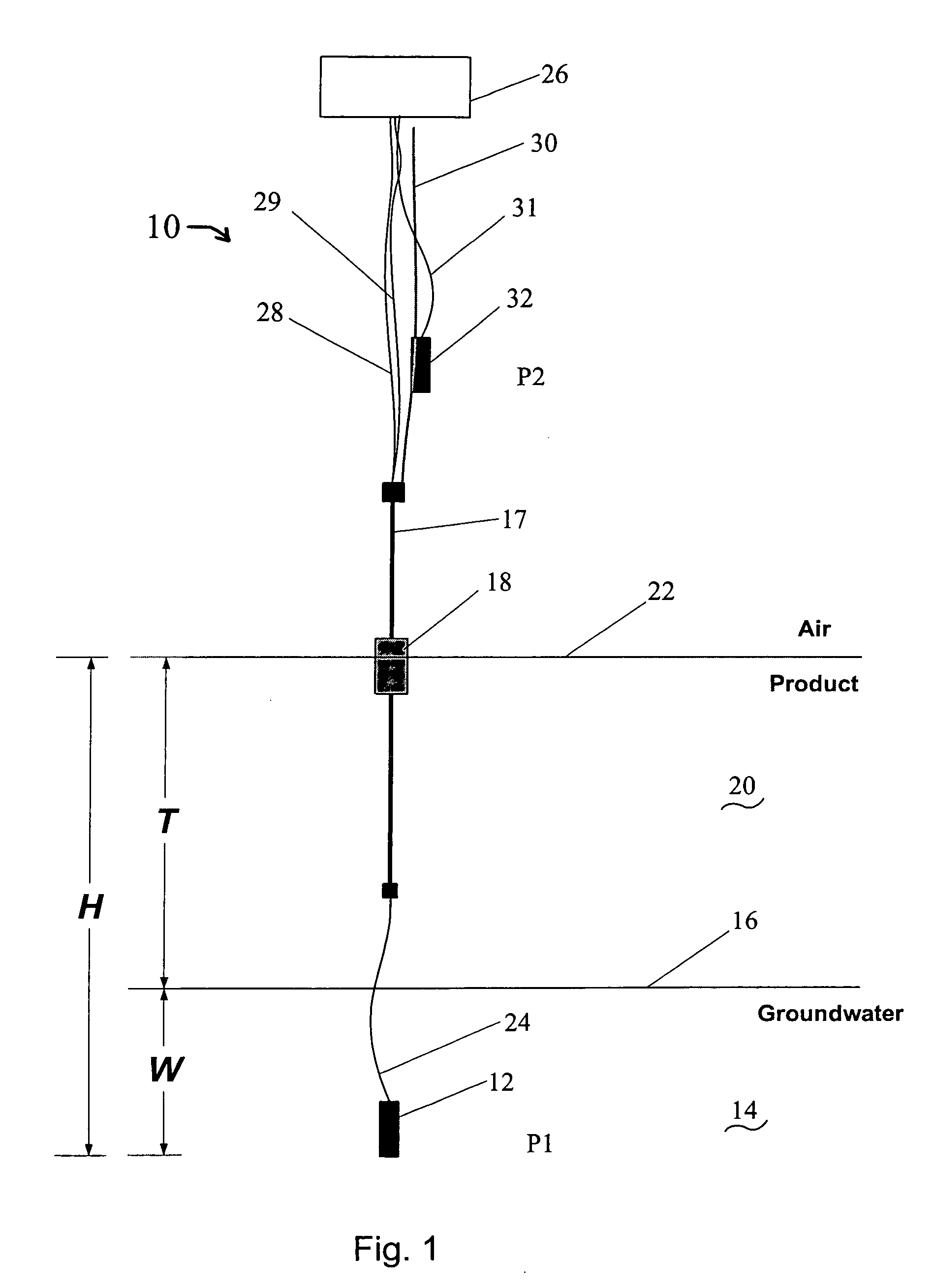
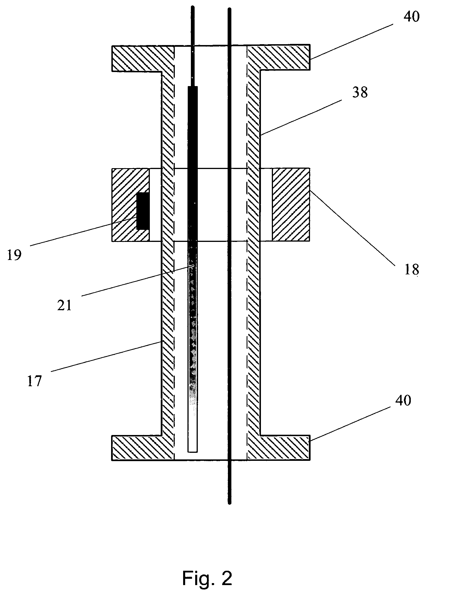
[0024]The present invention is a method of monitoring dual-phase liquid and interface levels that utilizes a dual-phase level monitoring (DPLM) instrument 10 to continuously monitor a dual-phase reservoir. The method is particularly well suited for groundwater monitoring wells with a light non-aqueous phase liquid (product) and tanks or vessels with dual-phase liquids and level monitoring and / or control issues. The DPLM Instrument 10 provides continuous signals of the level of a top fluid surface and the hydrostatic pressure below the fluid column. The DPLM instrument 10 can be used in wells and vessels operating at a positive or negative pressure relative to atmosphere in addition to being used in wells and vessels that operate at ambient (atmospheric) pressure. An optional configuration also provides a continuous signal for the pressure above the fluid column. When the DPLM instrument 10 is properly configured and positioned, the signals are processed to determine the product laye...


PUM


Abstract

A dual-phase level monitoring (DPLM) instrument that provides continuous signals that enables determination of the location of the top surface of the lighter of two immiscible fluids (the product) and the hydrostatic pressure below the total fluid column of both immiscible fluids. By knowing the fluid specific gravities, the output signals are processed to yield the location of the air / product and liquid / liquid interfaces, and the depth of the lighter phase. The instrument is intended for use in groundwater monitoring wells with a light non-aqueous phase liquid (product) and tanks or vessels with dual-phase liquids and level monitoring and / or control issues. The DPLM instrument includes a first pressure transducer situated beneath the surface of the liquid with a greater specific gravity, which will typically be ground water. A level element with a float selected so as to be buoyant and float on the surface of the lighter fluid is positioned above the first pressure transducer. A signal from the level element is proportional to the position of the float or the total distance the float is positioned above the bottom of the level element and therefore the total distance above the first pressure transducer, the pressure transducer located in the heaver liquid phase. A second pressure transducer can be deployed above the surface of the liquid if greater accuracy of measurement (as compared to assuming ambient pressure) is desired.

Description

BACKGROUND OF THE INVENTION[0001]1. Field of the Invention[0002]The present invention relates generally to methods of measuring levels of liquids, and more particularly is method utilizing an automatic dual-phase instrument for continuously monitoring a dual-phase reservoir.[0003]2. Description of the Prior Art[0004]Currently, only manual measuring techniques are commonly used to measure liquid levels in a reservoir containing at least two immiscible liquids, such as in environmental monitoring wells. In environmental monitoring wells, it is desirable to measure the thickness of a free-product (product) layer, the depth-to-product (dtp), and the depth-to-groundwater (dtw). The measurements are most typically performed using a manual interface probe. The interface probe consists of a sensor attached to a signal / support cable (which is typically marked in graduations of 0.01 feet) that is wound around a hand reel. The sensor is capable of differentiating between the free-product and g...

Claims


Application Information

Patent Timeline
IPC IPC(8): G01N9/00G01N9/26G01F23/14G01F23/74
CPCG01F23/14G01F23/74G01N9/26
Inventor ROBBINS, BRYCE V.
Owner ROBBINS BRYCE V
Learn More