
Method and apparatus for producing ammonia (NH3)

a technology of ammonia and ammonia gel, which is applied in the direction of arsenic compounds, silicon compounds, separation processes, etc., can solve the problems of constant difficulty in the aftertreatment of exhaust gas produced by the motor, and the temperature level of exhaust gas decreases

Inactive Publication Date: 2005-08-16
MAN NUTZFAHRZEUGE AG
View PDF8 Cites 106 Cited by
  • Summary
  • Abstract
  • Description
  • Claims
  • Application Information

AI Technical Summary

Benefits of technology

[0027]Due to the above-noted reasons, an exhaust gas after treatment system in which the reduction means in the form of ammonia (NH3), such as is provided by the invention, is introduced in gas form into the exhaust gas stream of the motor, offers enormous advantages. Also, the danger of undesired ammonia (NH3) slip is significantly reduced as compared with the introduction of an aqueous urea solution.
[0035]The reduction means ammonia (NH3) produced via the inventive method and the inventive apparatus, is introduced at suitable locations into the exhaust gas system of a motor, a gas turbine, or a burner, and, in fact, is introduced upstream of an SCR catalyzer or upstream of several SCR catalyzers, built into a muffler and disposed for exhaust gas flow therethrough in a parallel manner, the respective catalyzer or catalyzers effecting a reduction of the nitric oxide contained in the exhaust gas. Since, in the event of the deployment of ammonia (NH3) in connection with internal combustion engines as a reduction means, exclusively ammonia (NH3) produced immediately prior to its introduction is exclusively introduced into the exhaust gas, the activity of the SCR catalyzer system in connection with a cold internal combustion engine, and in connection with the warming up of the internal combustion engine, is decidedly improved, in comparison to those other methods in which urea would be bound into an exhaust gas stream as a solution or as a powder, for the reason that the fill condition of the ammonia (NH3) amount stored in the SCR catalyzer system can already be brought to a level favoring a rapid initiation of the nitrogen oxide reduction immediately following the start up of the cold internal combustion engine.

Problems solved by technology

In attempting to improve the fuel usage characteristic of the motor, the conditions for the after treatment of exhaust gas produced by the motor becomes continuously more difficult in that the exhaust gas temperature level diminishes.

Method used


Image

  • Method and apparatus for producing ammonia (NH3)
  • Method and apparatus for producing ammonia (NH3)
  • Method and apparatus for producing ammonia (NH3)

Examples


Embodiment Construction

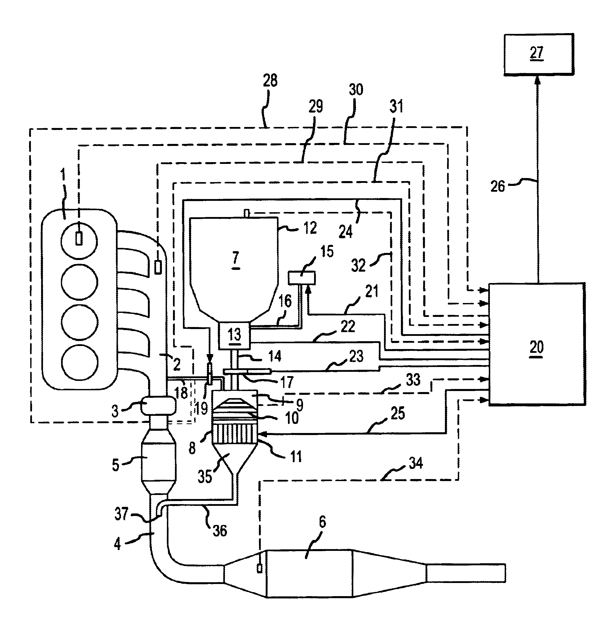
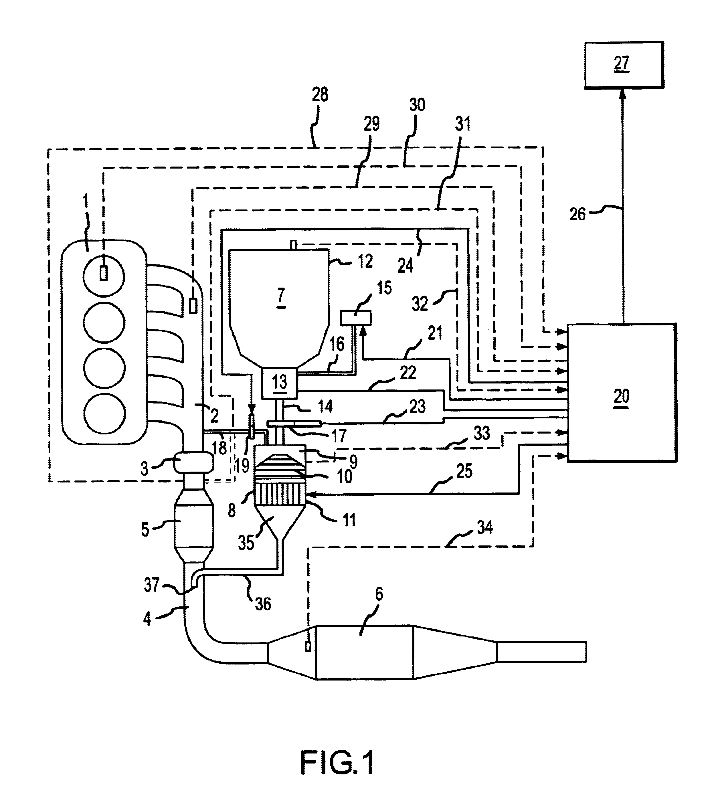
[0042]FIG. 1 shows an example of an arrangement in which the exhaust gas produced therefrom is to be subjected to a follow-on exhaust gas handling or treatment, the arrangement being comprised of an internal combustion engine 1 which is the drive source for, for example, a motor vehicle or a stationary facility. The exhaust gas of the internal combustion engine 1 flows along an exit path initially through outlet channels, thereafter through an exhaust gas manifold communicated with the outlet channels, and subsequently into an exhaust gas collection conduit 2 which is connected to the turbine 3 of a not-further described exhaust gas turbocharger. The outlet of the turbine 3 is communicated with an exhaust gas conduit 4 on which is disposed, at a location adjacent the turbine, a pre-catalyzer 5 and located downstream from the pre-catalyzer 5 is an SCR catalyzer 6 or several SCR catalyzers, built into a muffler and disposed for exhaust gas flow therethrough in a parallel manner. The p...


PUM


Abstract

A method is provided for producing ammonia (NH3) and introducing the produced ammonia (NH3) into an exhaust gas stream as a reduction means for selectively catalytically reducing nitrogen oxides contained in the exhaust gas stream, which is an exhaust stream generated by the combustion process of a motor, a gas turbine, or a burner. The method comprises feeding dry urea from a supply container in a controlled amount to reactor and subjecting the dry urea in the reactor to a sufficiently rapid thermal treatment such that a gas mixture comprising the reaction products of ammonia (NH3) and isocyanic acid (HCNO) is created. Also, the method comprises immediately catalytically treating the thus produced gas mixture in the presence of water such that the isocyanic acid (HCNO) resulting from the rapid thermal treatment is converted, via quantitative hydrolysis treatment, into ammonia (NH3) and carbon dioxide (CO2).

Description

BACKGROUND OF THE INVENTION[0001]The present invention relates to a method and an apparatus for producing ammonia (NH3) and introducing the produced ammonia (NH3) into an exhaust gas stream as a reduction means for selectively catalytically reducing nitrogen oxides contained in the exhaust gas stream, which is an exhaust stream generated by the combustion process of a motor, a gas turbine, or a burner.[0002]Ammonia (NH3) serves in the above-noted applications of interest as a reduction means which is introduced, as viewed relative to the exhaust gas flow, upstream of a special SCR catalyzer or catalytic converter, or upstream of an integrated group of SCR catalyzer modules, disposed for exhaust gas flow therethrough in a parallel manner, built into a muffler in the exhaust gas conduits of internal combustion engines, gas turbines, or burners or introduced into SCR catalyzer systems in which a reduction of the nitrogen oxides contained in the exhaust gas is effected. The term “SCR” m...

Claims


Application Information

Patent Timeline
IPC IPC(8): B01D53/86B01D53/90B01D53/94C01C1/00C01C1/02C01C1/08F01N3/20
CPCB01D53/8631B01D53/90B01D53/9431C01C1/02C01C1/086F01N3/2066F01N2240/25F01N2240/40F01N2610/02F01N2610/06F01N2610/10Y02E20/14Y02T10/24Y02P20/129F17C11/00Y02A50/20Y02T10/12
Inventor JACOB, EBERHARDKAFER, SEBASTIANMULLER, WERNERLACROIX, ANDREASHERR, ANDREAS
Owner MAN NUTZFAHRZEUGE AG
Learn More