
Imaging using a multifocal aspheric lens to obtain extended depth of field

Inactive Publication Date: 2005-08-09
UNIVERSITY OF ROCHESTER
View PDF7 Cites 262 Cited by
  • Summary
  • Abstract
  • Description
  • Claims
  • Application Information

AI Technical Summary

Benefits of technology

[0007]It is an object of the present invention to provide an improved system, method, and apparatus for capturing and processing images to provide an extended depth of field using a circularly symmetric multifocal aspheric lens.
[0008]It is another object of the present invention to provide an improved system, method, and apparatus for capturing an image through a circularly symmetric multifocal lens to provide a blurred image and processing of the blurred image in accordance with the point spread function of the lens to provide a recovered image in which one or more objects in a range of distances are in focus in accordance with the multifocal lengths of the lens.
[0010]It is still another object of the present invention to provide a camera with an extended depth of field to avoid the need for mechanical focusing required by prior art cameras to focus on objects at any particular distance.

Problems solved by technology

In conventional digital camera photography, object or objects in an image of a scene are in focus at one distance (or distance range) from the camera often results in other objects at other distances in the same scene being out of focus.
This is especially the case when imaged objects are at different distances close to the camera, such as within 10 feet or less, where optimal focus may be limited to a single limited distance range.
However, the focusing mechanism does not prevent objects outside this distance range being out of focus in the image.

Method used


Image

  • Imaging using a multifocal aspheric lens to obtain extended depth of field
  • Imaging using a multifocal aspheric lens to obtain extended depth of field
  • Imaging using a multifocal aspheric lens to obtain extended depth of field

Examples


Embodiment Construction

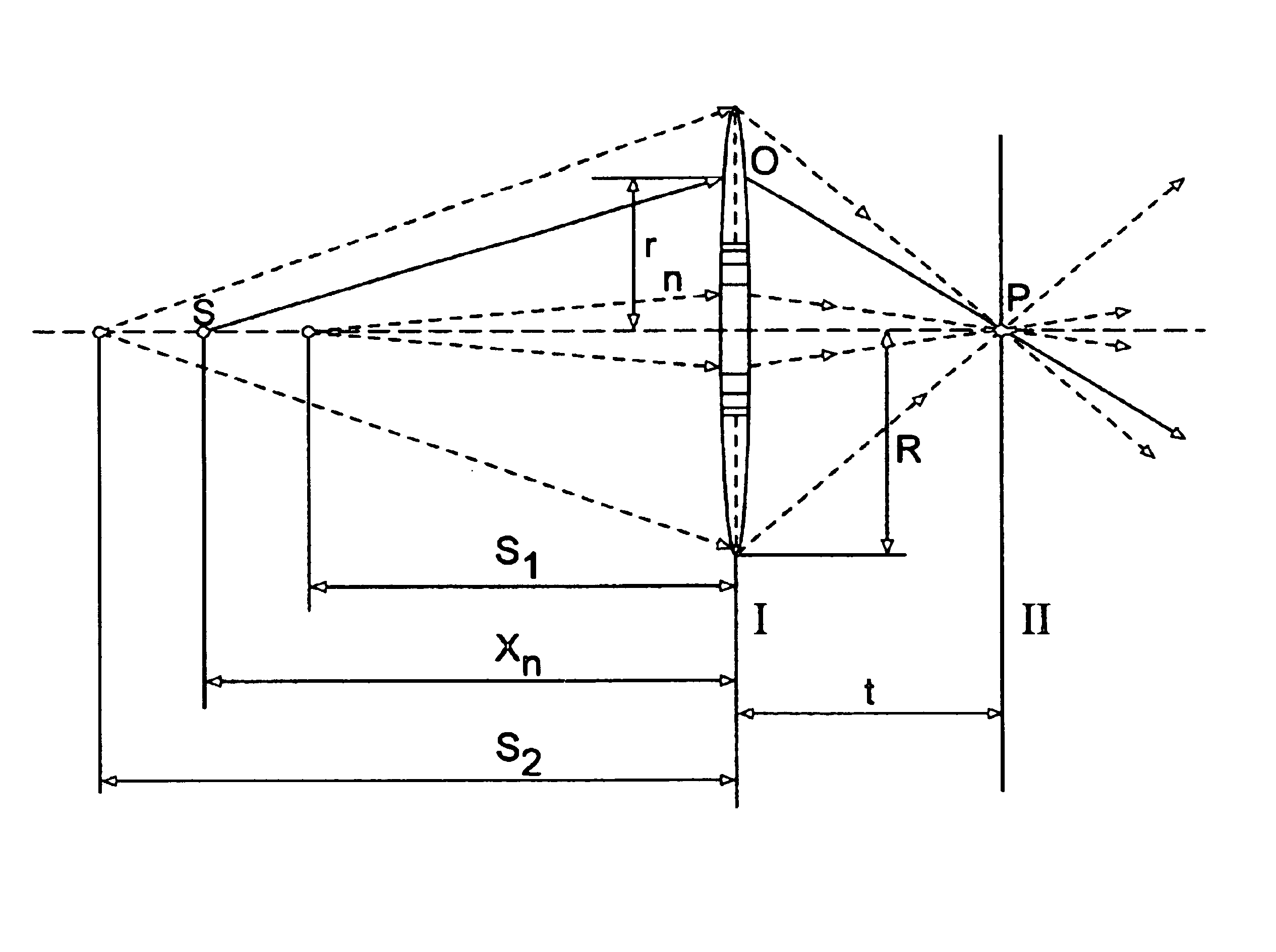
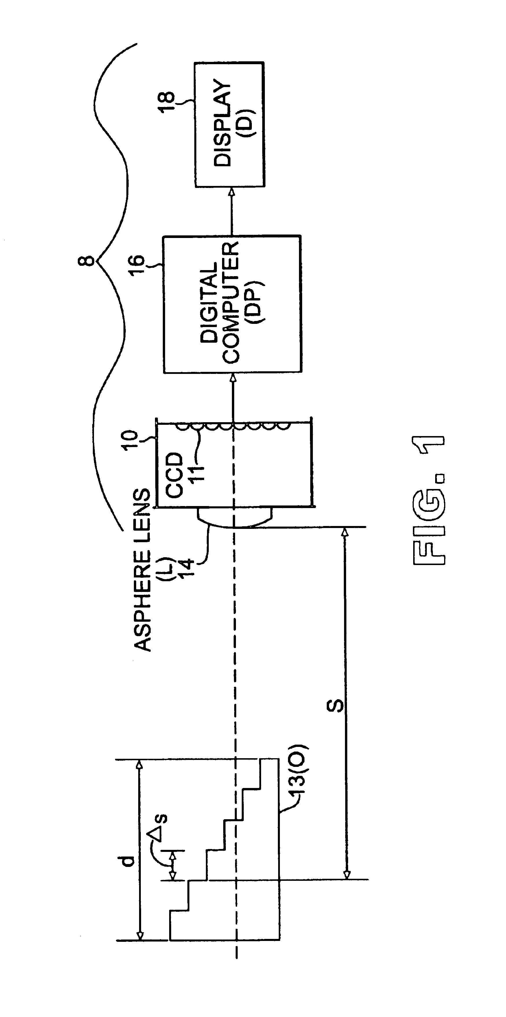
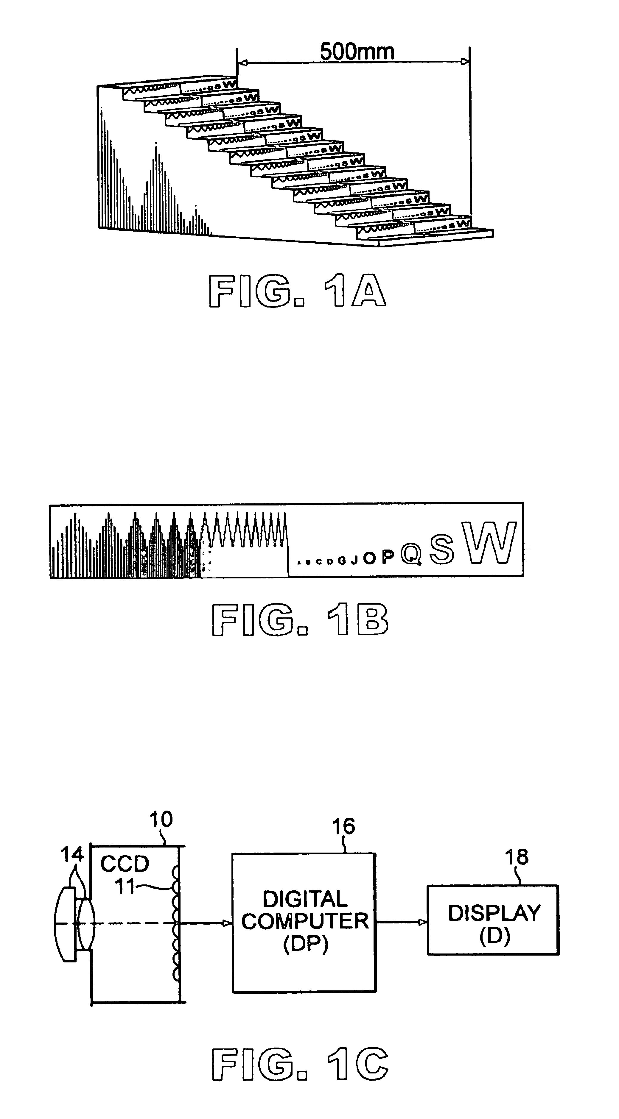
[0037]Referring to FIGS. 1 and 1A, an integrated imaging and processing system 8 is shown having a digital camera (or image capturing unit) 10 with a CCD array detector 11 for capturing images of an object 13 through a multifocal lens 14. The multifocal lens 14 represents a circularly symmetric lens with a focal length that various continuously with radius, so that for a 3-dimensional object or objects, over a desired distance range there is always an annular portion of the lens that provides a sharp in focus image, and the remainder of the lens contributes to blurring. Such a lens 14 represents an aspheric lens, and is hereinafter referred to as logarithmic asphere lens 14, and was designed using the Fermat's principle to find the transmission function for a lens that will image an extended portion of the object-optical-axis into a single image point. For purposes of illustration the object 13 is shown as a single three-dimensional object, such as a staircase, but object 13 may rep...


PUM


Abstract

A system for imaging with a circularly symmetric multifocal aspheric lens is provided for obtaining an extended depth of field. The system includes a camera for capturing an image of at least one object through a circularly symmetric multifocal aspheric lens to provide a blurred image, and a computer system for processing the captured blurred image to provide a recovered image of the object having an extended depth of field. The recovered image may be outputted to a display or other peripheral device. Processing of the blurred image utilizes one of inverse filtering, convolution matrix (e.g., edge sharpening matrix), or maximum entropy. The computer system performing image processing may be in the camera or represent a computer system external to the camera which receives the blurred image. The extended depth of field is characterized by the object being in focus over a range of distances in the recovered image.

Description

DESCRIPTION[0001]This application claims the benefit of priority to U.S. Provisional Patent Application No. 60 / 341,580, filed Dec. 18, 2001, which is herein incorporated by reference.[0002]The U.S. Government has rights in this invention pursuant to grant no. DAAD 19-00-1-0551 from U.S. Department of Defense / U.S. Army Research Office.FIELD OF THE INVENTION[0003]The present invention relates to a system, method, and apparatus for imaging using a multifocal aspheric lens to obtain extended depth of field, and in particular to a system, method, and apparatus using a circularly symmetric multifocal aspheric lens to obtain a blurred image and then processing of the blurred image to provide a recovered image having an extended depth of field over which object or objects in the image are in focus. The present invention also relates to a new class of lenses having a logarithmic phase function, which are circularly symmetric, multifocal, and aspheric.BACKGROUND OF THE INVENTION[0004]In conve...

Claims


Application Information

Patent Timeline
IPC IPC(8): G02B13/18G02B3/10G02B3/04G02B13/00G02B27/00G06T1/00G06T5/20H04N5/225H04N5/232H04N101/00
CPCG02B3/04G02B3/10G02B13/18G02B27/0075H04N5/2254H04N5/23229H04N23/55H04N23/80
Inventor GEORGE, NICHOLASCHI, WANLI
Owner UNIVERSITY OF ROCHESTER
Learn More