
Method of making a spark plug

a technology of spark plugs and electrodes, applied in the field of making spark plugs, can solve the problems of large difference in linear expansion coefficient, affecting the effect of linear expansion coefficient, and easy separation of noble metal chips and electrode main bodies, and achieves the effect of increasing the melting depth, increasing the melting point, and increasing the melting poin

Inactive Publication Date: 2005-08-02
NGK SPARK PLUG CO LTD
View PDF15 Cites 41 Cited by
  • Summary
  • Abstract
  • Description
  • Claims
  • Application Information

AI Technical Summary

Benefits of technology

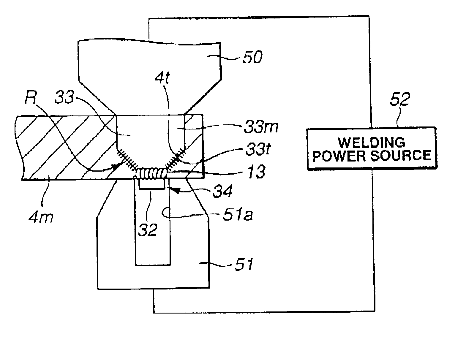
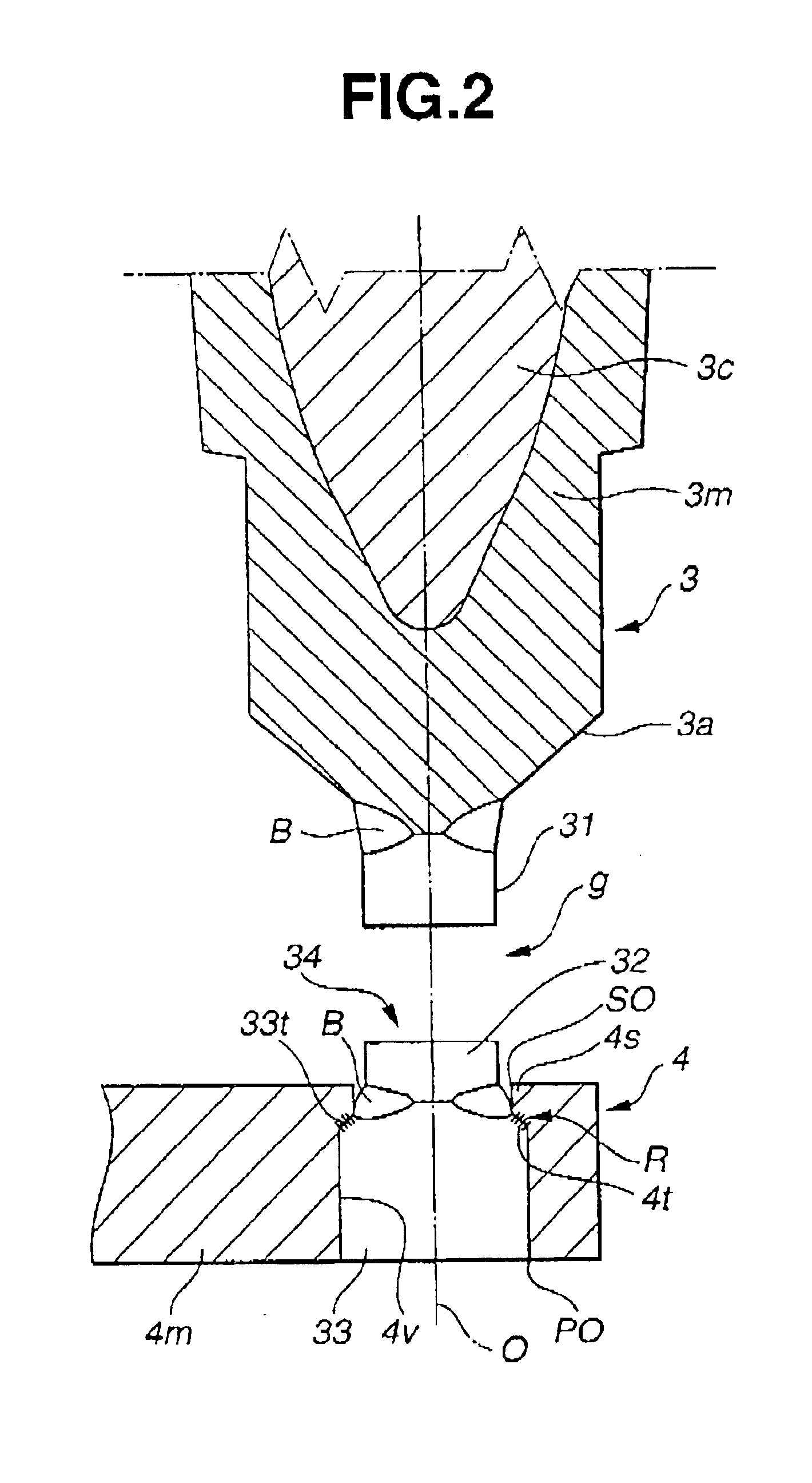
[0007]To accomplish the above object, the present invention provides a method of making a spark plug that includes a ground electrode having an electrode main body and a noble metal chip joined to the electrode main body by interposing therebetween an intermediate member, the noble metal chip being disposed so as face a center electrode and define therebetween a spark discharge gap, the method comprising the steps of prior to joining the noble metal chip to the electrode main body, joining the intermediate member and the noble metal chip together and thereby forming a noble metal chip and intermediate member assembly, placing the noble metal chip and intermediate member assembly on the electrode main body in a way as to allow the intermediate member to contact the electrode main body, and welding the electrode main body and the intermediate member of the noble metal chip and intermediate member assembly together while restricting relative movement of the electrode main body and the intermediate member of the noble metal chip and intermediate member assembly without applying an urging force to a joint between the intermediate member and the noble metal chip by using an another member.
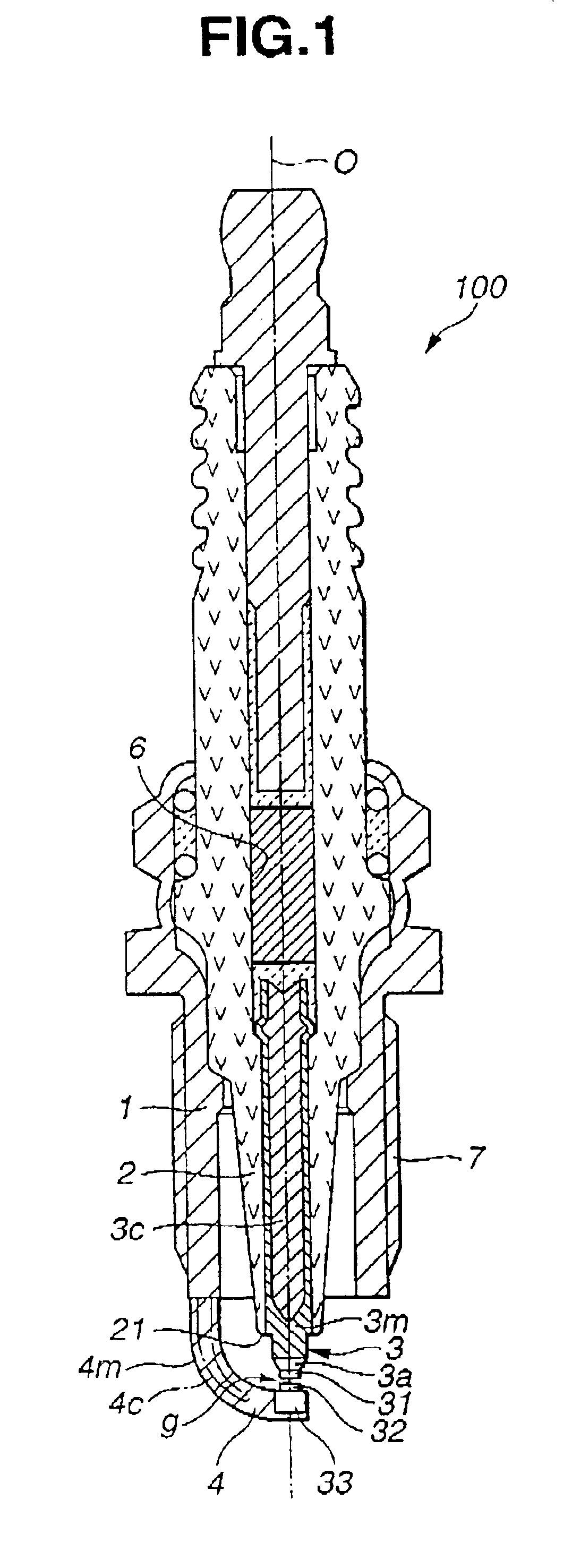
[0015]Further, by forming the intermediate member from a metal having a coefficient of linear expansion that is intermediate between those of the metals forming the noble metal chip and the electrode main body, a bad influence caused by the difference in the coefficient of linear expansion can be reduced as compared with the case where the noble metal chip is directly joined to the electrode main body, thus making it possible to prevent cracks or separation from being caused at the joint between the noble metal chip and the intermediate member more effectively.

Problems solved by technology

However, by this method, an excessively large compressive force is applied to the joining surfaces of the noble metal chip and the electrode main body at the time of welding, so that a defect such as cracks is liable to remain in the joining interface between the noble metal chip and the electrode main body after welding, thus possibly causing a problem that the noble metal chip and the electrode main body are easily separated from each other when subjected to cyclic heating and cooling.
However, since the noble metal chip made of an Ir system alloy has a high melting point, a defective joining interface is liable to be caused between the noble metal chip and the electrode main body due to insufficient melting, etc. when joined by resistance welding, thus causing a problem that the above-described cracks or separation is liable to occur.
Further, other than the insufficient melting, a large difference in the coefficient of linear expansion between the Ir system alloy constituting the noble metal chip and the Ni system alloy constituting the ground electrode main body is a cause of the cracks and separation.
However, if the noble metal chip and the electrode main body are welded by resistance welding with the intermediate member being interposed therebetween and by applying thereto a high compressive force, cracks or separation is liable to be caused at the joining portions of the intermediate member and the noble metal chip when the intermediate member cuts largely into the electrode main body together with the noble metal chip, thus being incapable of solving the above problem satisfactorily.

Method used


Image

  • Method of making a spark plug
  • Method of making a spark plug
  • Method of making a spark plug

Examples


example

[0060]In order to confirm the effect of the method according to the present invention, the following experiments were made. Ir-40Rh alloy (i.e., an alloy containing Ir as a major component and 40 wt % of Rh) was prepared as a material for forming the noble metal chip 32 on the ground electrode 4 side. A work or ingot of this alloy was hot-forged at 1500° C., then hot-rolled or hot-swaged at 1300° C. and further hot-drawn at 1200° C. to give an alloy wire of 1.4 mm in diameter. The wire was cut and thereby formed into a chip in the form of a circular disk of the diameter of 1.4 mm and of the thickness of 0.6 mm. Further, the intermediate member 33 was made of Ir-40Ni alloy (i.e., alloy containing Ir as a major component and 40 wt % of Ni) and formed into a circular disk of the diameter of 2.2 mm and the thickness of 0.6 mm. The both were joined together by laser beam welding and thereby formed into the noble metal chip and intermediate member assembly 34 shown in FIG. 13A. The noble ...


PUM

PropertyMeasurementUnit
diameteraaaaaaaaaa
thicknessaaaaaaaaaa
diameteraaaaaaaaaa

Abstract

A method of making a spark plug having a noble metal chip joined to an electrode main body of a ground electrode by interposing therebetween an intermediate member. The method comprises the steps of prior to joining the noble metal chip to the electrode main body, joining the intermediate member and the noble metal chip together, placing a noble metal chip and intermediate member assembly on the electrode main body in a way as to allow the intermediate member to contact the electrode main body, and welding the electrode main body and the intermediate member together while restricting relative movement of the electrode main body and the intermediate member without applying an urging force to a joint between the intermediate member and the noble metal chip.

Description

BACKGROUND OF THE INVENTION[0001]The present invention relates to a method of making a spark plug.[0002]A number of spark plugs of the kind in which a noble metal tip made of a metal containing Pt, Ir or the like as a major component is welded to an end of an electrode in order to improve the resistance to spark consumption have heretofore been proposed. Since a center electrode side whose polarity is frequently set negative at the time of spark discharge is subjected to strong attack of spark and liable to be consumed, a noble metal chip can produce a striking effect when used in the center electrode. However, as application of such spark plugs to high-output engines or lean-bum engines increases, a noble metal chip is employed increasingly also in the ground electrode side so as to meet the requirement that the ground electrode side has a high resistance to spark consumption. Heretofore, the noble metal chip on the ground electrode side is made of a Pt system alloy and welded to a...

Claims


Application Information

Patent Timeline
Patent Type & Authority Patents(United States)
IPC IPC(8): H01T21/02H01T21/00H01T13/20
CPCH01T21/02Y10T29/5193Y10T29/5195
Inventor MATSUBARA, YOSHIHIROHIRAMATSU, SHINICHIISHIKAWA, MASAHIROKAWAMURA, KAZUMI
Owner NGK SPARK PLUG CO LTD
Learn More