
Printer with reinforcing cover and ink tube fixing portions

a printing machine and reinforcing cover technology, applied in printing, instruments, measurement devices, etc., can solve the problems of reducing the print quality of a recording sheet by the print head, the frame the kinking or twisted effect of the print head, so as to reduce the height of the recording unit, reduce the rigidity and strength of the frame, and achieve high rigidity and strength. the effect of the fram

Active Publication Date: 2005-08-02
BROTHER KOGYO KK
View PDF4 Cites 14 Cited by
  • Summary
  • Abstract
  • Description
  • Claims
  • Application Information

AI Technical Summary

Benefits of technology

[0010]The invention provides a printer that can ensure high rigidity and strength of a frame of a recording unit even in a printer, of which the size is shrunk, to maintain print quality. The invention also provides a printer that can facilitate paper jam clearing, and a printer where ink tubes, which extend from ink cartridges disposed outside the recording unit to a print head, can be arranged in an orderly manner within a frame of a recording unit.
[0013]As the cover body is fixed to the frame so as to block a part of the opening of the frame, the frame is reinforced at a place other than the window of the cover body, thereby enhancing the rigidity and strength of the frame and the cover body. Especially, even when the height of the recording unit is decreased, the rigidity and strength of the frame can be maintained. Thus, if the frame of the recording unit is fixed to a mounting frame of the printer, the tendency to form a kink in the frame is reduced, so that the moving path of the print head can be normalized, thereby maintaining high print quality.
[0016]As compared with a printer in which an ink cartridge sits atop a carriage, the printer of the invention can be shrunk in its height by reducing the height of the recording unit. Decreasing the height of the recording unit may reduce the rigidity and strength of the frame. However, the cover body is fixed to the frame to maintain high rigidity and strength of the frame (and the cover body), thereby reducing the tendency to form a kink, or twist, in the frame and providing high print quality.
[0017]Preferably, in the printer according to the invention, an end portion of the window of the cover body with respect to the main scanning direction may be formed in a round shape similar to a curve in the ink tube approaching the end portion of the window. Thus, the ink tube is less prone to project above and out of the end portion of the window and less prone to be caught at the end portion of the window. Further, even if the ink tube projects above and out of the window and moves atop the cover body, it can be easily returned inside the recording unit via the window. Thus, the carriage can be normally moved in the main scanning direction, and damage to the ink tube can be prevented.
[0018]Preferably, in the printer according to the invention, a guide portion that guides the ink tube downward when the carriage is moved in the main scanning direction may be provided around an edge portion of the window of the cover body. When the carriage is moved in the main scanning direction and the ink tube is moved in conjunction with the carriage and nearly projects out from the window, the guide portion guides the ink tube downward to protect the ink tube from projecting out from the window.
[0019]Further, in the printer according to the invention, it is preferable that the window of the cover body is defined in such a shape as to be able to cover the upper portion of the fixing portion with the cover body. Inside the recording unit, the ink tube of which is fixed at the fixing portion can be covered with the cover body, so that the ink tube is less prone to project out from the window.

Problems solved by technology

When rigidity and strength of a recording unit frame are low, the frame of the recording unit, which is fixed to a frame attaching portion of a printer, may become kinked or twisted.
For example, a moving path of a print head may deviate from its normal moving path, thereby causing a reduction in print quality on a recording sheet by the print head.
However, paper jam clearing and print head replacement may become difficult.
If an opening is merely defined in the top surface of the frame of the recording unit, to enable paper jam clearing and print head replacement, it is difficult to sufficiently enhance the rigidity and strength of the frame.
Especially when the height of the recording unit is decreased, it is difficult to dispose the ink tubes within the recording unit in order to keep out of the way of the carriage's sideways movement.

Method used


Image

  • Printer with reinforcing cover and ink tube fixing portions
  • Printer with reinforcing cover and ink tube fixing portions
  • Printer with reinforcing cover and ink tube fixing portions

Examples


Embodiment Construction

[0032]An embodiment of the invention will be described in detail with reference to the accompanying drawings. In the embodiment, the invention is applied to a multifunction apparatus that includes various functions, such as a telephone, a facsimile machine, a printer, a scanner, and a copier. However, it can be applied to any printing apparatus using liquid ink printing.

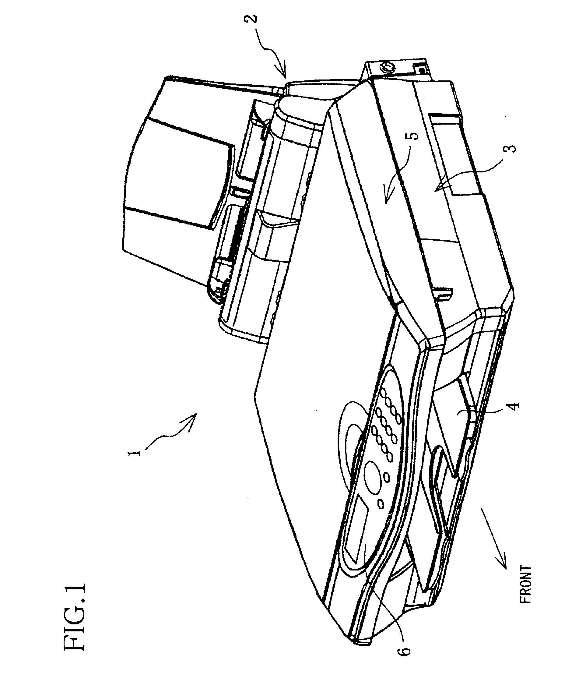
[0033]As shown in FIG. 1, a multifunction apparatus 1 is provided with a paper feed unit 2 disposed at an rear end thereof, a printer 3 disposed at a front bottom part of the paper feed unit 2, a discharge paper tray 4 disposed at the front of a recording unit (FIG. 2) of the printer 3, a scanner 5 disposed on the printer 3, and an operation panel 6 disposed at the front end of and on the top surface of the scanner 5.

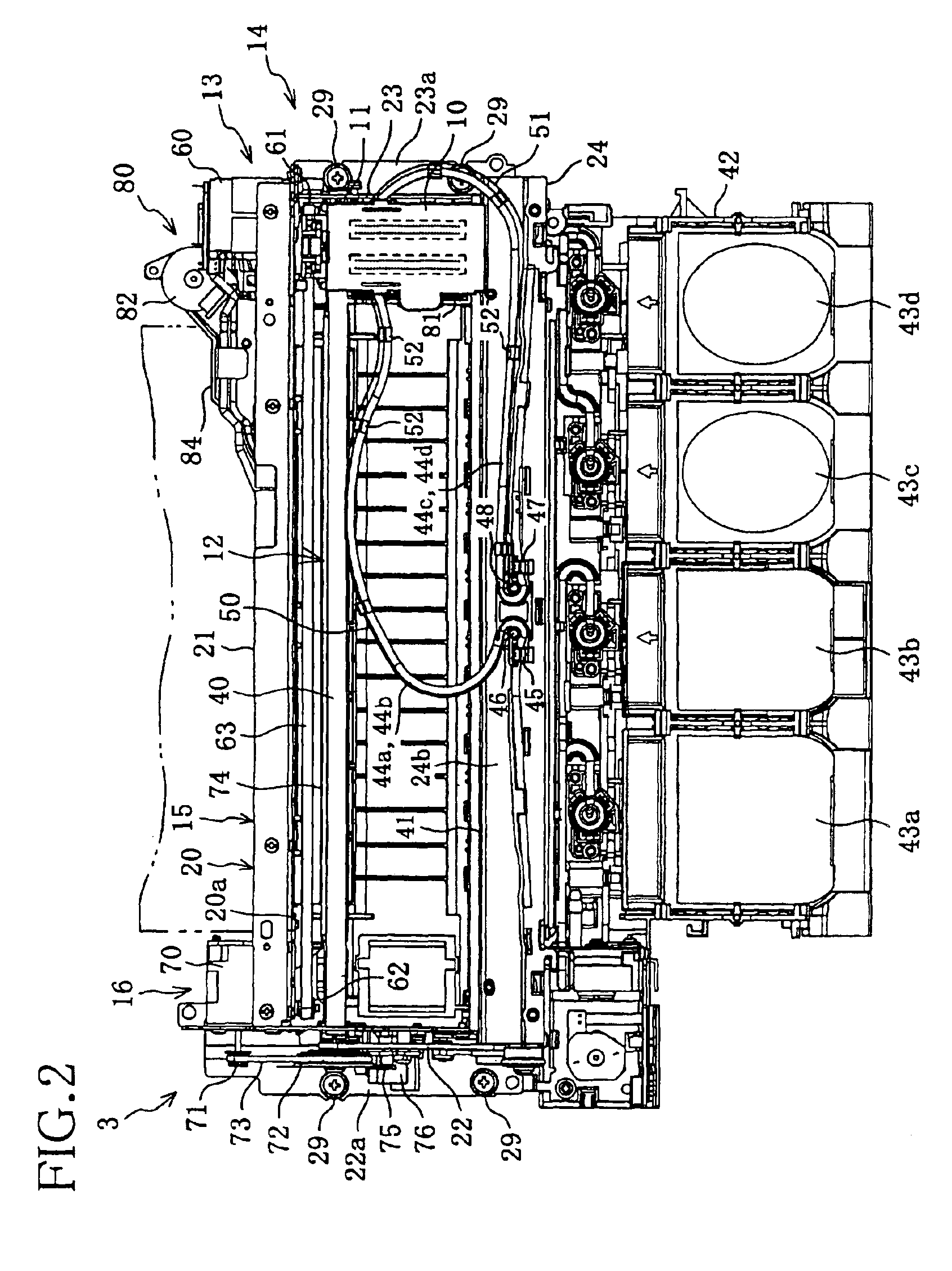
[0034]The printer 3 will be described. As shown in FIGS. 2 to 6, the printer 3 includes a print head 10, a carriage 11 that mounts the print head 10, a guide mechanism 12 that guides and supports the car...


PUM


Abstract

A recording unit frame, in which a recording unit is to be mounted, includes a frame and a cover body. The frame surrounds a scanning area of a carriage in which recording onto a recording sheet is performed by a print head, and accommodates a guide mechanism and a carriage moving mechanism. The frame has at least an opening on its top. The cover body is fixedly attached to the frame so as to block a part of the opening of the frame. The cover body has a window that enables a user to have access to a recording sheet in the frame. With these structures, the recording unit can be shrunk in height without losing its rigidity and strength, thereby providing a printer capable of maintaining high print quality.

Description

BACKGROUND OF THE INVENTION[0001]1. Field of Invention[0002]The invention relates to a printer and, more particularly, to an improved structure of a recording unit including a frame in which a print head performs recording onto a recording sheet.[0003]2. Description of Related Art[0004]A known printer is provided with a recording unit, which is made up of a print head, a carriage that carries thereon the print head, a guide mechanism that guides the carriage movably in a main scanning direction, and a carriage moving mechanism that moves the carriage in the main scanning direction. In most cases, a pair of side frames and a main frame, connecting the side frames, are assembled so as to form the shape of substantially an angular C letter, and a platen that supports a recording sheet being printed is disposed between the side frames. The main frame is provided with the carriage moving mechanism and one of the side frames is provided with a sheet conveying mechanism that feeds recordin...

Claims


Application Information

Patent Timeline
Patent Type & Authority Patents(United States)
IPC IPC(8): B41J29/02B41J2/175B41J29/393B41J2/01
CPCB41J2/175B41J29/02B41J29/393
Inventor KOGA, YUJI
Owner BROTHER KOGYO KK
Learn More