
Security paper, method and device for checking the authenticity of documents recorded thereon

a security paper and document technology, applied in the field of security paper, method and device for checking the authenticity of documents recorded thereon, can solve the problems of inability to manufacture technology to anchor the small transponder chip on the bank note, and inability to meet the needs of forgers' advances in working methods, etc., to achieve the effect of simple manufacturing of safety paper and simple straight form

Inactive Publication Date: 2005-07-19
INFINEON TECH AG
View PDF16 Cites 43 Cited by
  • Summary
  • Abstract
  • Description
  • Claims
  • Application Information

AI Technical Summary

Benefits of technology

[0020]Because of its simple straight form, the dipole antenna makes possible a simple manufacture of the safety paper. In particular, it can be realized as a straight linear strip across a large paper web, wherein the individual dipole antennas of the documents to be produced from the paper web by cutting are produced automatically by the cutting process. The sending / receiving directional characteristic connected with the dipole antenna is also advantageous. For example, bank notes which are stacked are conventionally counted in counting machines such that the respectively uppermost bank note of the stack is turned about one of its longer lateral edges and is then placed onto a new stack. Inasmuch as the dipole antenna extends perpendicularly to this lateral edge, it passes during this turning process through a plane which extends perpendicularly to the stack plane so that, for a suitable alignment of the sending / receiving characteristic of the counting machine, the coupling for the bank note, aligned during the turning movement perpendicularly to the stack plane, is at a maximum and a feedover of the other bank notes of the stack is suppressed. It is understood that the modulated carrier frequency used for the signal transmission is adjusted to the size of the dipole antenna.
[0021]Various possibilities are conceivable in regard to how to realize the circuit chip and its dipole antenna on the safety paper. Preferably, it is suggested that the pattern which forms the dipole antenna is comprised of two conductor strips extending along a common straight line which are contacted via their oppositely positioned ends with connecting areas of the circuit chip. In this connection, it is particularly expedient that the two conductor strips are formed by portions of an insulating thin polymer substrate strip that have been made conducting between whose insulating portion, delimited by the ends of the conductor strips facing one another, the circuit chip is arranged. The conducting portions of the insulating thin polymer substrate strips can be generated, for example, by doping. It is also very expedient to metallize, i.e., to provide with a thin metal layer, a larger polymer web with the exception of the insulating portions serving for receiving the circuit chips and to produce the polymer substrate strips therefrom by cutting. In the case of producing the conductivity by metallization of one side of the polymer substrate strip, the other side can be provided, as an additional measure, with a photovoltaic layer which can serve as an exclusive or additional supplier of operational energy for the circuit. Furthermore, it is expedient to provide the conductor strip with cutouts, in particular, fine perforations, so that the clamping action with the paper layer is improved.

Problems solved by technology

These conventional measures, however, can no longer be considered satisfactory in view of the advances of the working means employed by forgers.
Accordingly, the resources employed for forgery are correspondingly great.
Moreover, it is difficult with regard to manufacturing technology to anchor the small transponder chip on the bank note.
The other aforementioned options, in which the antenna coil is arranged outside of the transponder chip on the bank note, provide the possibility of forming greater coil cross-section but the formation and connection of the antenna coil to the transponder chip on the bank note is problematic with regard to manufacturing technology.

Method used


Image

  • Security paper, method and device for checking the authenticity of documents recorded thereon
  • Security paper, method and device for checking the authenticity of documents recorded thereon
  • Security paper, method and device for checking the authenticity of documents recorded thereon

Examples


Embodiment Construction

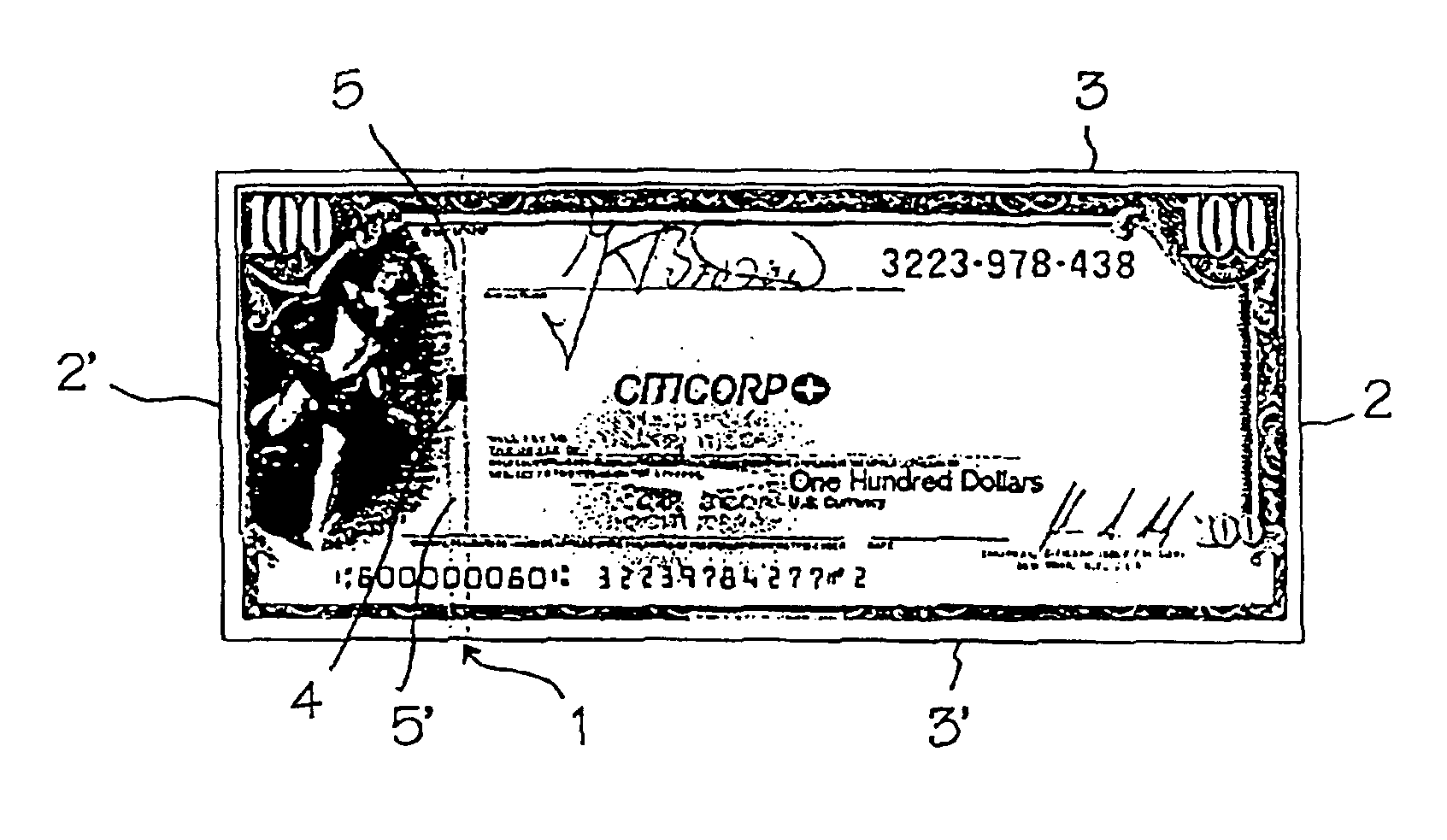
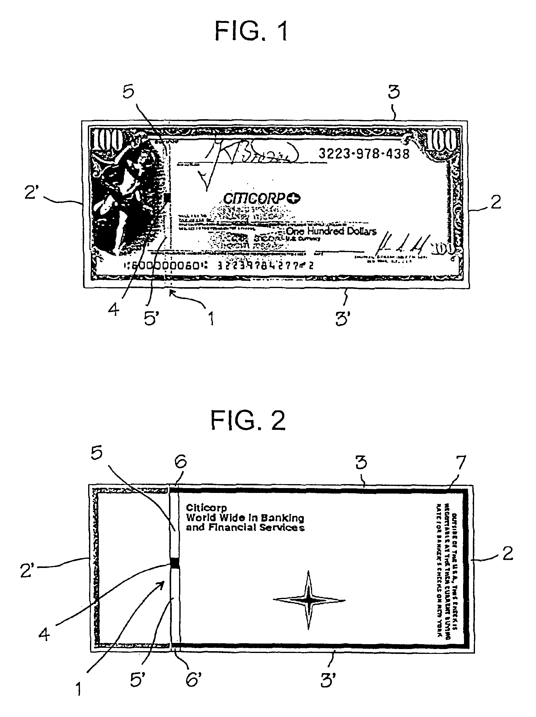
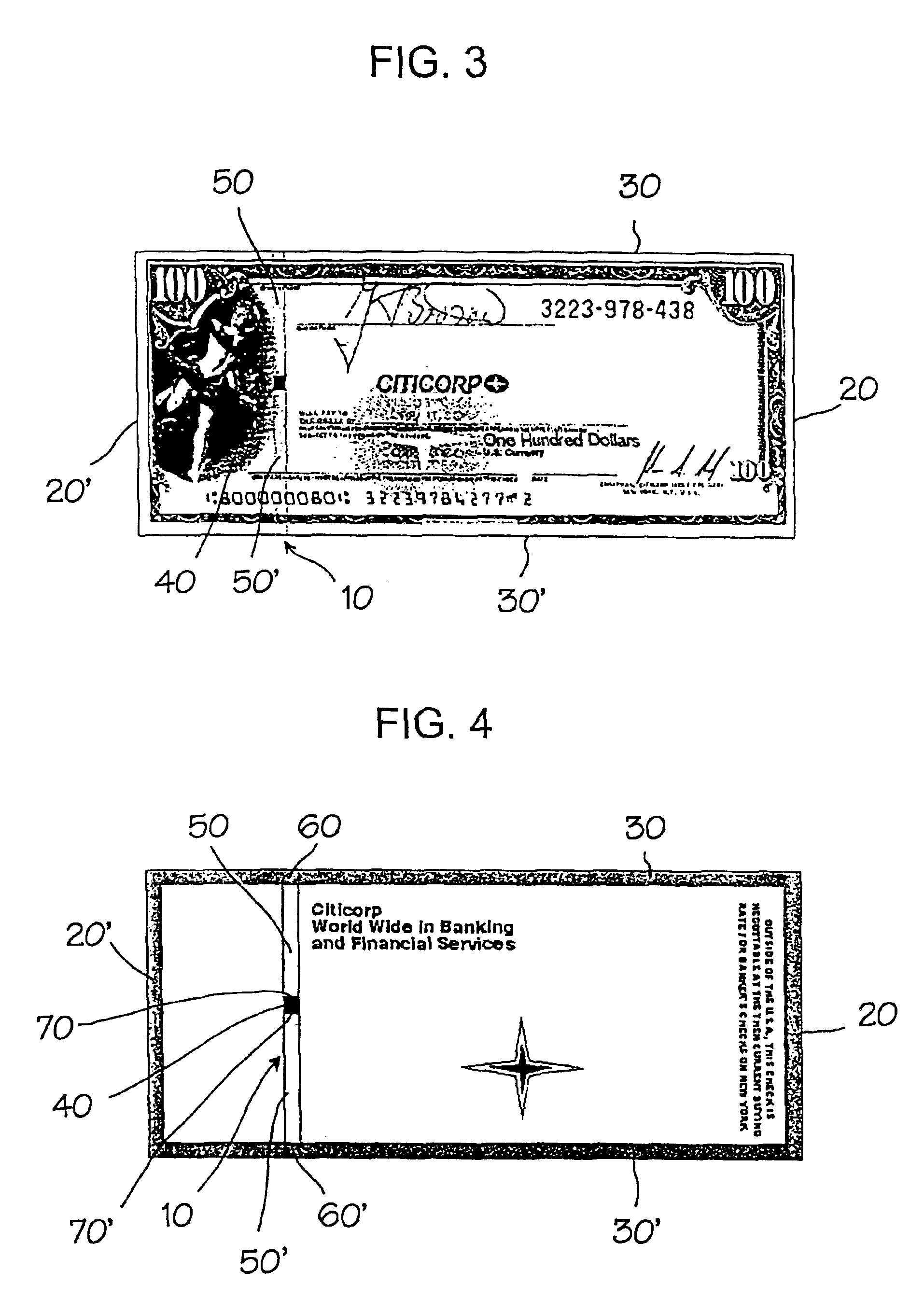
[0037]The travelers check of an internationally known bank illustrated in the drawing is supplemented for the purpose of explaining the invention by the schematic illustration of an electronic circuit. The latter has a polymer strip 1 which is made conductive by doping and is embedded in the paper layer. This can be realized in a manner known in the art in that during the paper manufacture first the first partial layer of the paper pulp is deposited, the polymer strip 1 is placed thereon, and, subsequently, a second partial layer of the paper pulp is applied. The polymer strip 1 extends parallel to the two shorter lateral edges 2, 2′ over the entire width of the rectangular travelers check up to its longer lateral edges 3, 3′. Even though the polymer strip 1 is covered on both sides by the paper layer, it is illustrated in the drawing so as to show through the layers covering it.

[0038]In the center of the polymer strip 1 an integrated polymer circuit chip is formed whose external te...


PUM


Abstract

A safety paper with an embedded electronic circuit (1, 4, 7) is used to create more effective forgery-proof securities such as bank notes. In order to check authenticity, a carrier-frequency signal is transmitted to the circuit and an output signal representing an authenticating feature is emitted from raid circuit in response to said input signal and detected.

Description

BACKGROUND OF THE INVENTION[0001]1. Field of the Invention[0002]The invention relates to a safety paper having a structure making possible a contactless checking of an authenticity feature and to a method for checking the authenticity of documents which are recorded in an optically readable form on the safety paper.[0003]2. Description of the Related Art[0004]The use of such safety papers for producing documents serves for protecting them against unauthorized reproduction by forgers. This is necessary, in particular, for securities such as bank notes, checks, travelers checks, stocks, etc. There is also a need for securing papers which do not have a direct monetary value, such as identification papers, passports etc., against unauthorized copying. The employed term “document” is therefore meant to include all types of securities and identification papers to be protected against unauthorized copying.[0005]In particular, in the case of securities which are circulated daily, for exampl...

Claims


Application Information

Patent Timeline
IPC IPC(8): B42D15/00G07D7/00G06K19/077B42D15/10G06K19/07G06K19/10G07D7/01G07D7/026G07D7/10G07D7/12
CPCG06K19/07749G06K19/07758G07D7/0093B42D25/29B42D25/355B42D2033/46G07D7/01G07D7/12B42D25/22
Inventor BROSOW, JOERGEN
Owner INFINEON TECH AG
Learn More