Power system with enhanced thermodynamic efficiency and pollution control

Inactive Publication Date: 2005-07-19
THERMOENERGY POWER SYST
View PDF32 Cites 90 Cited by
  • Summary
  • Abstract
  • Description
  • Claims
  • Application Information

AI Technical Summary

Benefits of technology

[0005]It is a further object of the present invention to provide a power plant or system offering enhanced thermodynamic efficiency.
[0015]It is a still further object of the present invention to provide a system of the above type that provides for the efficient partial oxidation or gasification of solid and liquid fossil fuels.

Problems solved by technology

Power plants or systems have achieved relatively high levels of efficiency and pollution control, but they are not without problems.
For example, as effluent particulate standards have become increasingly difficult to meet, power plants have typically required a number of different processes and pieces of equipment to remove particulate matter.
This adds to the cost and complexity of the system, and these processes and pieces of equipment typically require substantial power input, leading to substantial parasitic power losses and inefficiencies.
Further, although power plants have occasionally used economizers and similar equipment to recover a portion of the sensible heat from the gases in the products of combustion, power plants have not attempted to recover the latent heat of vaporization of such gases because, under operating conditions of such plants, the condensation temperatures of such gases are too low to be efficiently recovered.
Particularly in a system in which a relatively large amount of gaseous water is produced during combustion, the failure to recover any significant portion of such latent heat of vaporization can lead to significant thermodynamic inefficiencies.

Method used


Image

  • Power system with enhanced thermodynamic efficiency and pollution control
  • Power system with enhanced thermodynamic efficiency and pollution control
  • Power system with enhanced thermodynamic efficiency and pollution control

Examples


Embodiment Construction

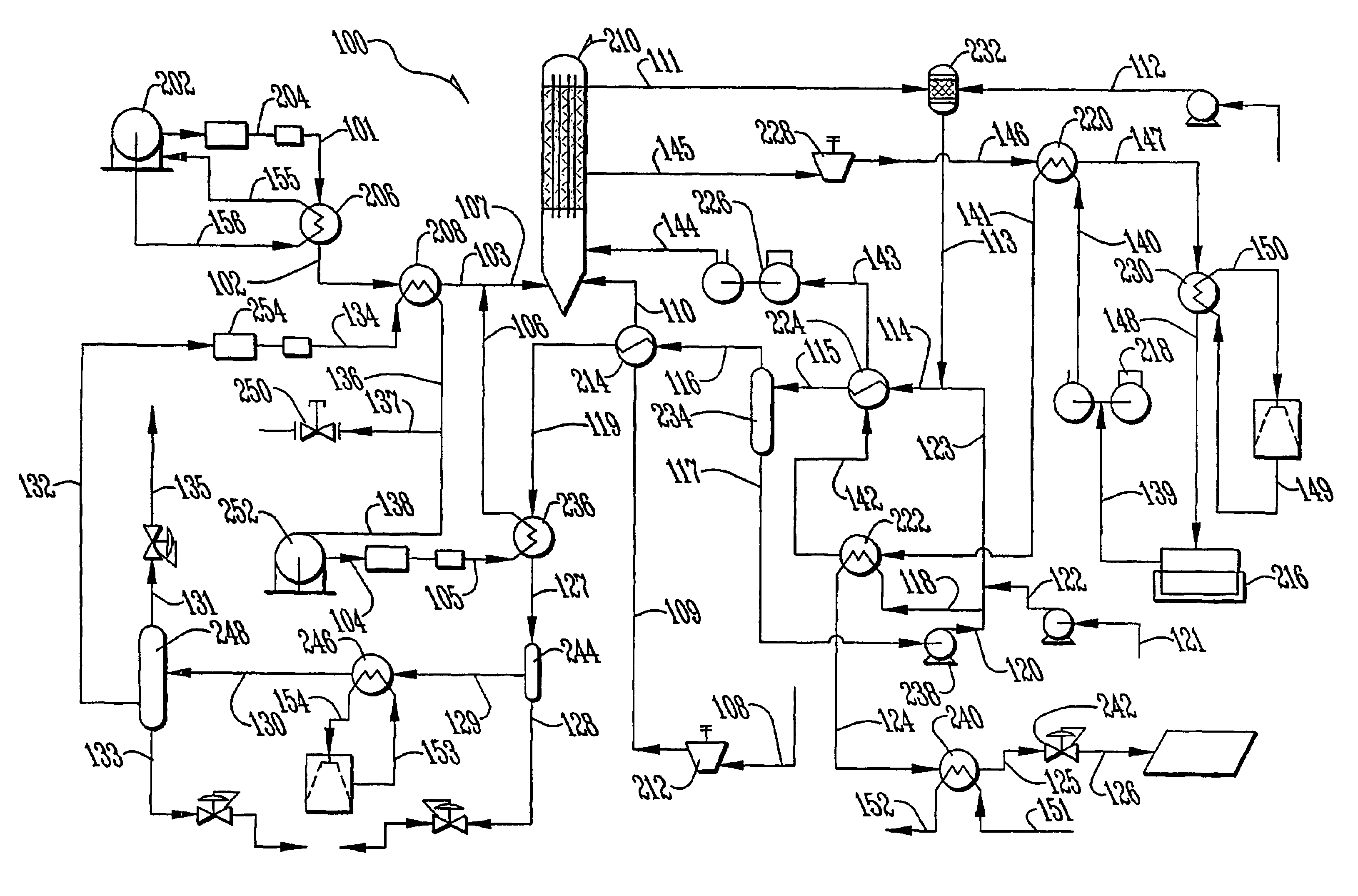
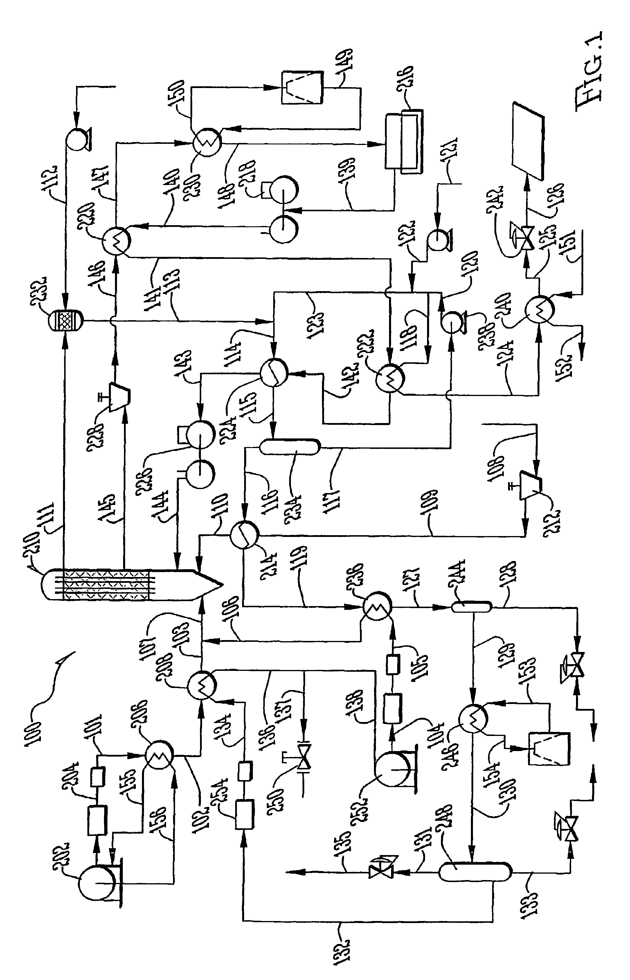
[0029]Referring to FIG. 1, the reference numeral 100 refers in general to an integrated power system of the present invention that integrates the combustion of fossil fuels and the efficient production of electricity with the recovery of liquid carbon dioxide and the elimination of acid gas and particulate emissions. Referring to FIGS. 1 and 2, liquid oxygen from tank 202 is pumped to system pressure by pump 204. For the system depicted in FIG. 1, the system pressure is preferably within a range of from approximately 700 psia to approximately 2000 psia and is more preferably substantially within a range of from approximately 850 psia to approximately 1276 psia. This pressure range allows one to use standard equipment designs and encompasses the critical pressure of carbon dioxide (1,071 psi or 7.382 MPascal). In the later stages of the system, when water and carbon dioxide are sequentially condensed, this elevated system pressure range allows carbon dioxide condensation at the highe...


PUM


Abstract

An elevated pressure power plant (100) for cleanly and efficiently oxidizing, gasifying or combusting a fuel. The fuel is oxidized or gasified in a reaction chamber (210) at a pressure range from approximately 700 psia to 2000 psia, or from approximately 850 psia to 1276 psia. Products of combustion from the chamber may be passed to a heat exchanger (224). A portion of the condensed water may be recycled to the products of combustion upstream of the heat exchanger. Also, before being passed to the reaction chamber, the coolant may be routed through the heat exchanger in a two-step pressure fashion.

Description

[0001]This application is a national phase application based upon PCT Application Ser. No. PCT / US01 / 01011, filed on Jan. 11, 2001, which is a continuation-in-part of utility patent application 09 / 483,677 filed Jan. 14, 2000, which issued on Mar. 6, 2001 as U.S. Pat. No. 6,196,000.BACKGROUND OF THE INVENTION[0002]This invention relates to a power plant or system, and more particularly, to a low-emission, fossil fuel power plant with enhanced thermodynamic efficiency and pollution control.[0003]In power plants, such as fossil fuel power plants, a fossil fuel is ignited and burned, oxidized or combusted within a reaction or combustion chamber under controlled conditions to generate heat. The heat is transferred to a circulating fluid, such as water, which flows through cooling tubes found in or adjacent to the reaction chamber, to generate steam. The steam is then passed through a steam turbine to generate electricity. Integrated Gasification Combined Cycle (IGCC) power plants using so...

Claims


Application Information

Patent Timeline
IPC IPC(8): F02C3/26F02C3/28F22B1/00F22B1/22F23J15/06F01K17/00
CPCF02C3/28F22B1/22F23J15/06F23J2219/70F23L2900/07001F23L2900/07008Y02E20/18Y02E20/322Y02E20/328Y02E20/363Y02E20/16Y02E20/32Y02E20/34Y02E20/30
Inventor FASSBENDER, ALEXANDER G.
Owner THERMOENERGY POWER SYST
Why Eureka
Try Eureka