Eureka AIR delivers breakthrough ideas for toughest innovation challenges, trusted by R&D personnel around the world.

Use of orthogonal or near orthogonal codes in reverse link

a reverse link and orthogonal technology, applied in the field of use of orthogonal or near orthogonal codes in reverse link, can solve the problems of attempting to achieve orthogonality, wasting time, and wasting resources,

Inactive Publication Date: 2005-07-12
IPR LICENSING INC
View PDF11 Cites 43 Cited by
  • Summary
  • Abstract
  • Description
  • Claims
  • Application Information

AI Technical Summary

Benefits of technology

[0012]It can particularly advantageous to support as high a data rate as possible on the reverse link of such a network that is carrying data on the reverse link, e.g., from the remote unit to the base station. Consider that existing digital cellular standards such as the IS-95 Code Division Multiple Access (CDMA) specify the use of different code sequences in a forward link direction in order to maintain minimum interference between channels. Specifically, such a system employs orthogonal codes on the forward link, which defines individual logical channels. However, the optimum operation of such a system requires all such codes to be time aligned to a specific boundary to maintain orthogonality at the receiver.
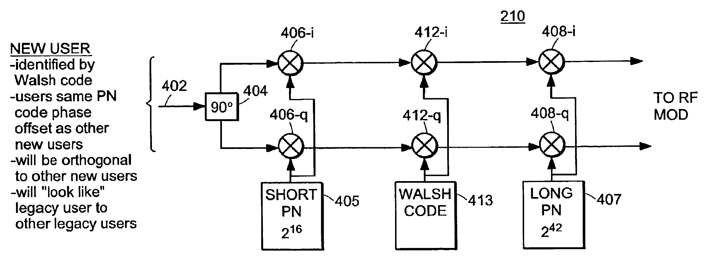
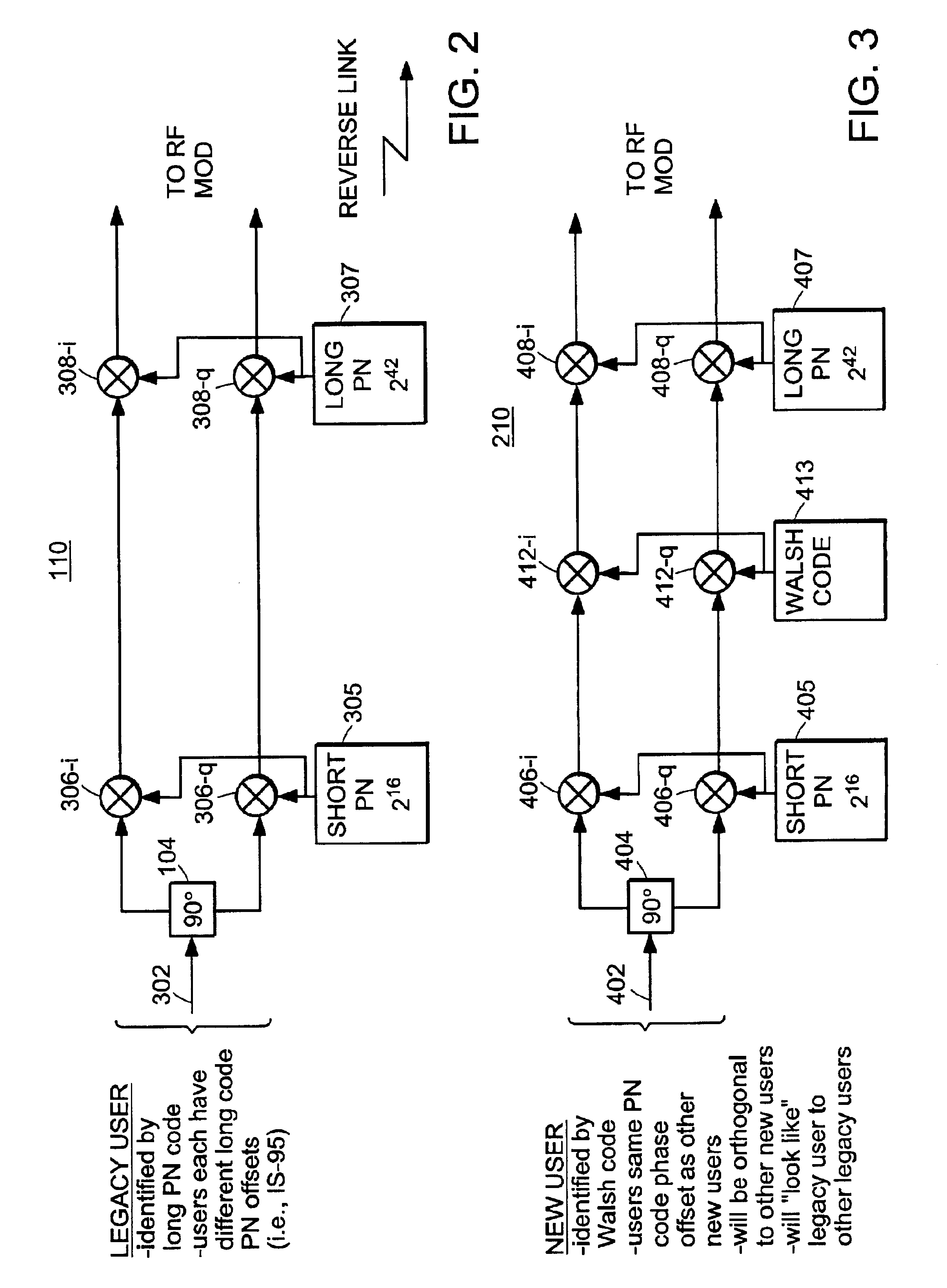
[0014]Another aspect of the present invention is a system supporting communication among members of a first group of users and a second group of users. The first group of users, which may be legacy users of a digital Code Division Multiple Access (CDMA) cellular telephone system, can encode their transmissions with a common first code. Such first group of users are uniquely identifiable by providing a unique code phase offset for each user. The second group of users, who may be users of a high speed data service, can encode their transmissions using the same code and one of the code phase offsets of that code. That is, a unique phase shifted long code can be used for spreading. Each of the users of the second group can further encode their transmissions with an additional code. This additional code can be unique for each of the users of the second group. This permits the transmissions of the second group of users to be orthogonal to each other while maintaining the appearance of collectively being a single user of the first group.

Problems solved by technology

In a reverse link, however, orthogonal codes are not used to transmit from a remote device to the base station because of the unique delay profile associated with each remote device for transmissions back to the base station.
More specifically, a signal transmitted by another remote device farther away typically takes longer to reach the base station than a transmission by a remote device closer to the base station.
Thus, orthogonality of channels can be lost when these signals are not received so that they are synchronized with respect to each other at the base station.
Current CDMA standards such as IS-2000 and IS-95 do not attempt to achieve orthogonality between separate remotely transmitting devices.

Method used


Image

  • Use of orthogonal or near orthogonal codes in reverse link
  • Use of orthogonal or near orthogonal codes in reverse link
  • Use of orthogonal or near orthogonal codes in reverse link

Examples


Embodiment Construction

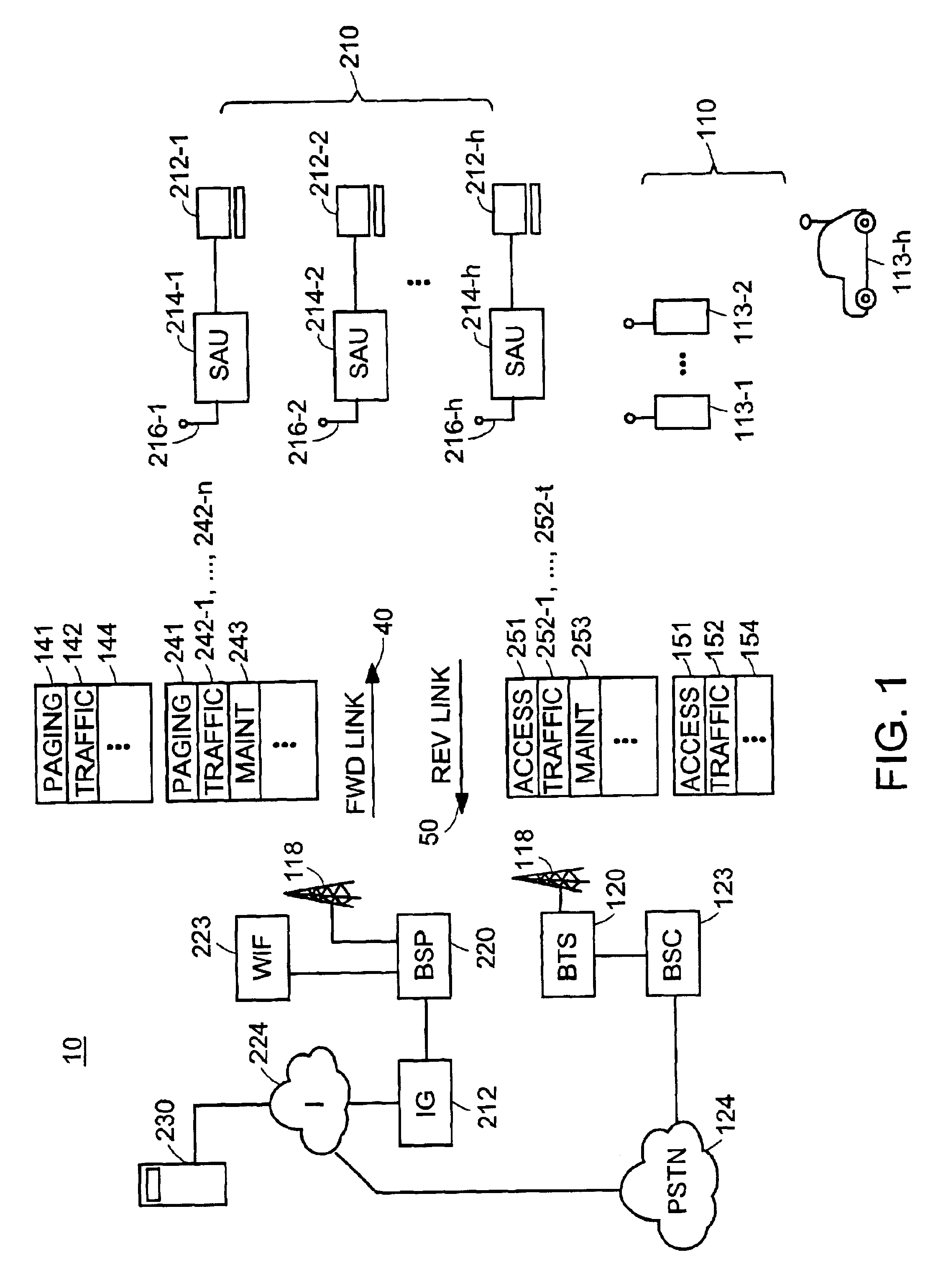
[0027]FIG. 1 is a block diagram of a Code Division Multiple Access (CDMA) communication system 10 that makes use of a signal encoding scheme in which a first class of logical channels are assigned unique long codes with different code phase offsets, and a second class of logical channels are provided by using a common code and common code phase offset, combined with an additional coding process using a unique orthogonal code for each channel. In one embodiment, however, communication system 10 does not include legacy users.

[0028]In the following detailed description of a preferred embodiment, the communication system 10 is described such that the shared channel resource is a wireless or radio channel. However, it should be understood that the techniques described here can be applied to implement shared access to other types of media such as telephone connections, computer network connections, cable connections, and other physical media to which access is granted on a demand driven b...


PUM


Abstract

A technique for allowing a first and second group of users to share access to a communication channel such as a wireless radio channel is disclosed. The first group of users can be a group of legacy users such as those that use digital CDMA cellular telephone equipment based on the IS-95 standard. The second group of users can be a group of web surfers that code their transmissions using one of multiple formats. The first group of users can share one modulation structure such as, on a reverse link, using unique phase offsets of a common pseudorandom noise (PN) code. The second group of users can share another modulation structure, but in a manner that is consistent and compatible with the users of the first group. Specifically, the users of the second group may all use the same PN code and code phase offset. Each channel used by the second group of users can be uniquely identified by a corresponding unique orthogonal code.

Description

RELATED APPLICATION(S)[0001]This application claims the benefit of U.S. Provisional Application No. 60 / 306,062, filed on Jul. 17, 2001, the entire teachings of which is incorporated herein by reference.BACKGROUND OF THE INVENTION[0002]The last twenty years have seen unprecedented growth in both the type and demand for wireless communication services. Wireless voice communication services, including cellular telephone, Personal Communication Services (PCS), and similar systems now provide nearly ubiquitous coverage. The infrastructure for such networks has been build-out to the point where most residents of the United States, Europe, and other industrialized regions of the world have not just one, but multiple service providers from which to choose.[0003]Continued growth in the electronics and computer industries increasingly contributes to demand for access to the Internet and the myriad of services and features that it provides. This proliferation in the use of computing equipment,...

Claims


Application Information

Patent Timeline
Patent Type & Authority Patents(United States)
IPC IPC(8): H04B1/707H04J11/00H04B1/7077H04J13/00H04J13/18H04W28/18H04W48/18H04W56/00H04W72/04
CPCH04B1/707H04J13/18H04J13/0022H04B1/7077H04J13/0048H04W88/08H04J3/0635H04L7/043H04W72/0446
Inventor PROCTOR, JR., JAMES A.ALAPURANEN, PERTTI O.
Owner IPR LICENSING INC
Why Eureka
Eureka Blog
Learn More