
Metal dome sheet, its manufacturing method, and metal dome system

Inactive Publication Date: 2005-07-12
THE FUJIKURA CABLE WORKS LTD
View PDF12 Cites 22 Cited by
  • Summary
  • Abstract
  • Description
  • Claims
  • Application Information

AI Technical Summary

Benefits of technology

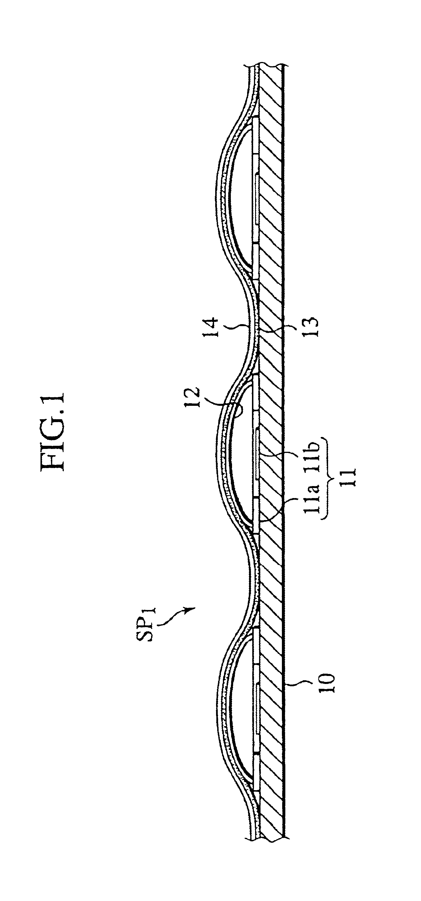
[0012]Specifically, a metal dome system according to the present invention basically has a structure similar to that shown in FIG. 1, in which an adhesive layer removed portion is provided at an adhesive layer portion between at least two adjacent metal domes so as to constitute an air escape portion. Alternatively, only part of the metal dome such as an upper portion thereof is adhered and fixed with an adhesive layer; meanwhile, a peripheral portion of a disposed region

Problems solved by technology

However, if such an air escape hole is provided and the air inside the dome is set open to the outside air, there is a problem that humidity or dust in the outside air is caught into the switch panel SP1.
However, installation of the spacer film 15 incurs an increase in the number of components and an increase in assembly

Method used


Image

  • Metal dome sheet, its manufacturing method, and metal dome system
  • Metal dome sheet, its manufacturing method, and metal dome system
  • Metal dome sheet, its manufacturing method, and metal dome system

Examples


Embodiment Construction

[0030]FIG. 7 shows one example of a low-profile operating switch panel adopting a metal dome system according to the present invention.

[0031]Basically, this switch panel SP3 has almost the same structure as the switch panel SP1 shown in FIG. 1. However, in the switch panel SP3, a constitution of an adhesive layer 23 to be formed on one side of a metal dome sheet 24A is largely different from the relevant constitution in the switch panel SP1. Note that a substrate 10, electrodes 11 and metal domes 12 of FIG. 7 severally have the same structures as those in FIG. 1.

[0032]In other words, the metal dome sheet 24A of the present invention is made of a film such as a polyethylene telephthalate. Moreover, as shown in FIG. 8 and FIG. 9, an adhesive layer removed portion 23a is provided on part of the adhesive layer 23 between at least two adjacent metal domes 12 to constitute a sort of a passage, and such a passage is defined as an air escape portion (passage) δ. Also, a peripheral portion 2...


PUM


Abstract

In a metal dome sheet to be hermetically adhered to a plurality of metal domes disposed at electrodes on a substrate and to other portions of the substrate via an adhesive layer, the present invention provides an adhesive layer removed portion at a portion of the adhesive layer between at least two adjacent metal domes as an air escape portion. Accordingly, it is possible to obtain a thin and light switch panel, which is also excellent in water resistance and dust resistance.

Description

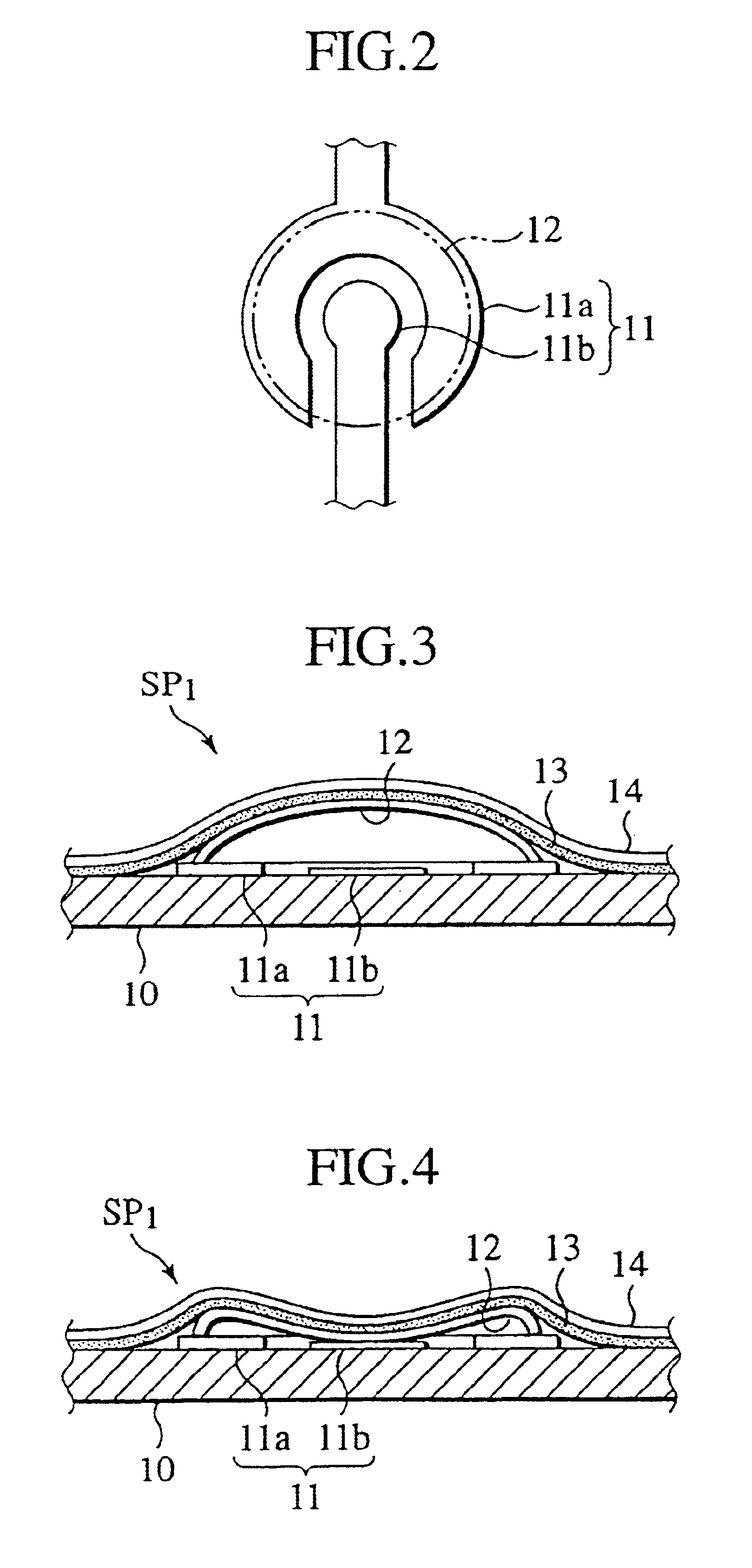
TECHNICAL FIELD[0001]The present invention relates to metal dome sheets for low-profile operating switch panels for use in electric and electronic instruments such as mobile telephones.BACKGROUND ART[0002]Various types of low-profile operating switch panels have been already proposed. For example, there are low-profile operating switch panels having structures as shown in FIG. 1 and FIG. 5.[0003]In a switch panel SP1 shown in FIG. 1, a plurality of metal domes 12 to be disposed at electrodes 11 on a substrate 10 are fixed with a film 14 adhered to the substrate 10 via an adhesive layer 13.[0004]Here, the metal dome 12 is usually made of an elastic hemispheric cap of metal. Moreover, as shown in FIG. 2 for example, the metal dome 12 is disposed on an electrode 11 including a pair of an arc electrode layer 11a and a straight electrode layer 11b guided therein (a thickness of this layer is made slightly lower than the electrode layer 11a, or an insulating layer is provided thereon). In...

Claims


Application Information

Patent Timeline
IPC IPC(8): H01H13/70H01H13/702H01H13/48H01H11/00
CPCH01H13/7006H01H13/702H01H2203/02H01H2203/038H01H2205/016H01H2205/026H01H2213/016H01H2221/002H01H2223/003H01H11/00
Inventor HIRAI, KOJIMATSUKAWA, TAKASHININOMIYA, KENJIKOSHIHARA, MASATOMO
Owner THE FUJIKURA CABLE WORKS LTD
Learn More