Self regulating rotor

a self-regulating, rotor technology, applied in the direction of wind motors with parallel air flow, rotary piston liquid engines, wind motors with perpendicular air flow, etc., can solve the problems of inconvenient use, limited range of wind speeds and inability to operate well for horizontal axis rotor windmills

Inactive Publication Date: 2005-06-28
KALISKI ARTHUR
View PDF11 Cites 27 Cited by
  • Summary
  • Abstract
  • Description
  • Claims
  • Application Information

AI Technical Summary

Benefits of technology

[0013]The primary object of the invention is to provide a rotor that will change into aerodynamically efficient shapes that will best match the conditions the rotor is operating in.
[0014]Another object of the invention is a simple designed rotor that will change its shape to best match changing wind speeds and weather conditions.
[0017]Yet another object of the invention is a rotor of simple design, with few moving parts, which lowers its cost of manufacture as well as increase the rotors dependability.
[0022]Yet another object of the invention is a rotor design that generates low noise levels when operating.
[0023]Still yet another object of the invention is to provide a low noise rotor that will operate in the disturbed air found around buildings and trees, ideally suited for used in urbane and populated areas.

Problems solved by technology

Horizontal axis rotor wind mills rotating at high speeds generate strong gyroscopic forces that make them not suitable for use in turbulent winds, where the wind continually changes direction.
Horizontal axis rotor wind mills will only operate in a limited range of wind speeds.
Horizontal axis rotor windmills are not designed to function well in the disturbed air flows that are found around buildings in cities and urban areas.
Horizontal axis rotor windmills need to be sited where the wind is of a minimum velocity and undisturbed to be practical.
Horizontal axis rotor wind mills need complex control mechanisms to control their speed of rotation as well as to feather their blades in extreme conditions.
The prior art rotors suffer in at least one respect.
For example, Wilson's U.S. Pat. No. 1,646,673 wind turbine is not automatically adjustable and uses a design of laterally shifting paired vanes to change exposed area to the wind.
Finally all of the foregoing devices have relatively complex construction which are expensive to assemble and maintain.

Method used


Image

  • Self regulating rotor
  • Self regulating rotor
  • Self regulating rotor

Examples


Embodiment Construction

[0052]Detailed descriptions of the preferred embodiment are provided herein. It is to be understood, however, that the present invention may be embodied in various forms. Therefore, specific details disclosed herein are not to be interpreted as limiting, but rather as a basis for the claims and as a representative basis for teaching one skilled in the art to employ the present invention in virtually any appropriately detailed system, structure or manner.

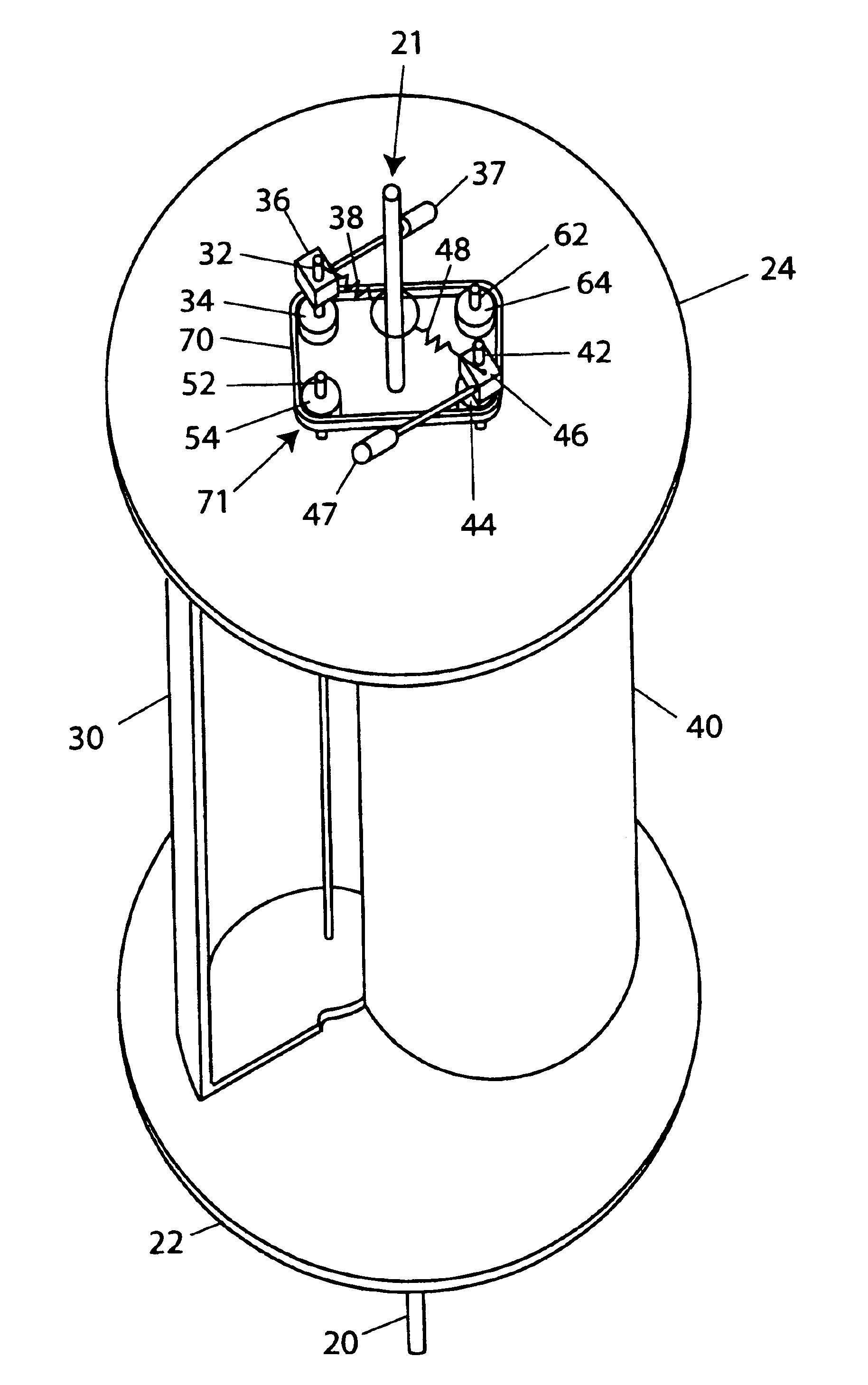
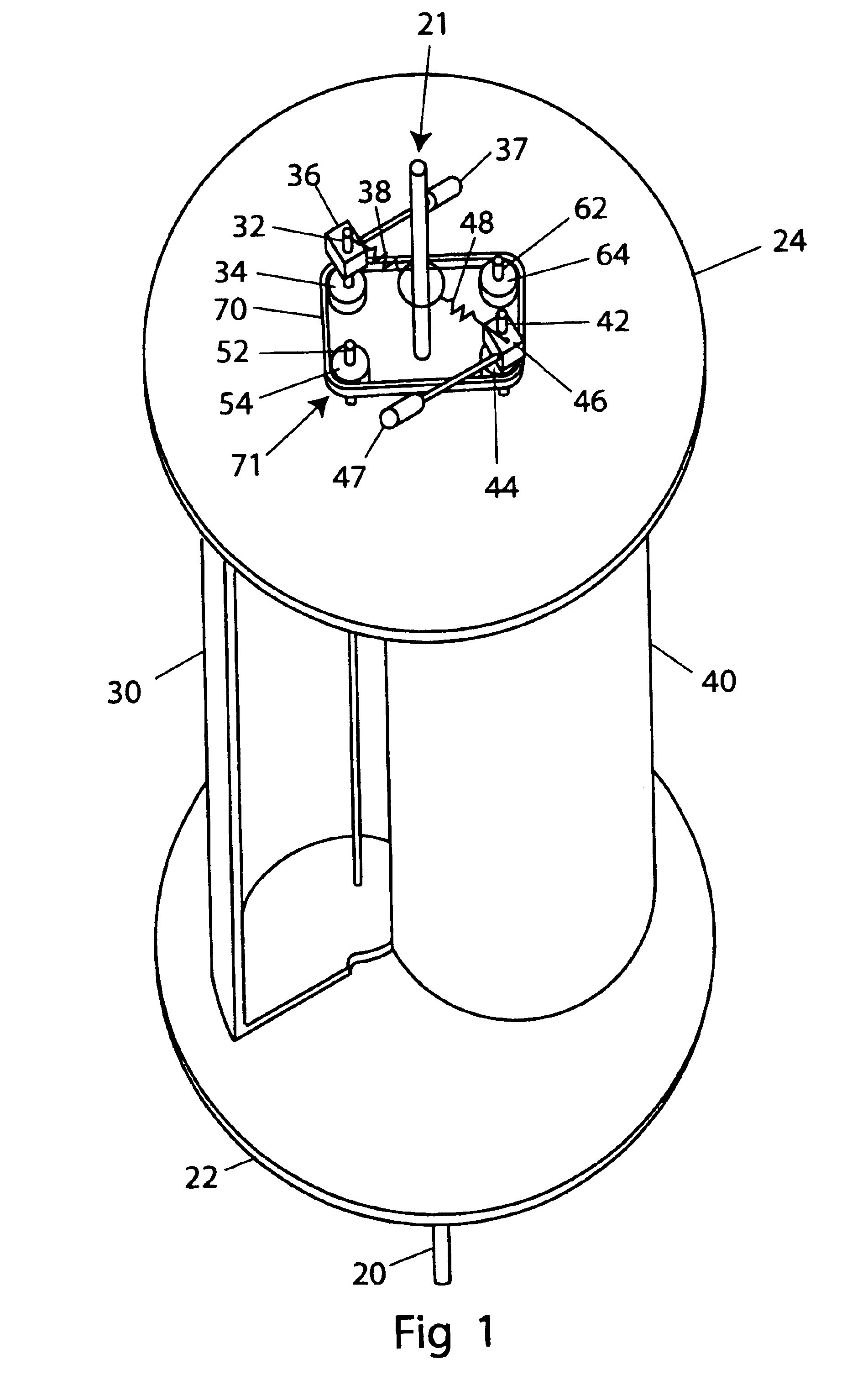
[0053]A preferred embodiment of the present invention is illustrated in FIG. 1 and FIG. 7. FIG. 1 shows a perspective view of a single rotor section and FIG. 7 shows a front perspective view of a two rotor section assembly. It is understood that the word cups in the specifications can also include vanes. We define a cup to include a vane.

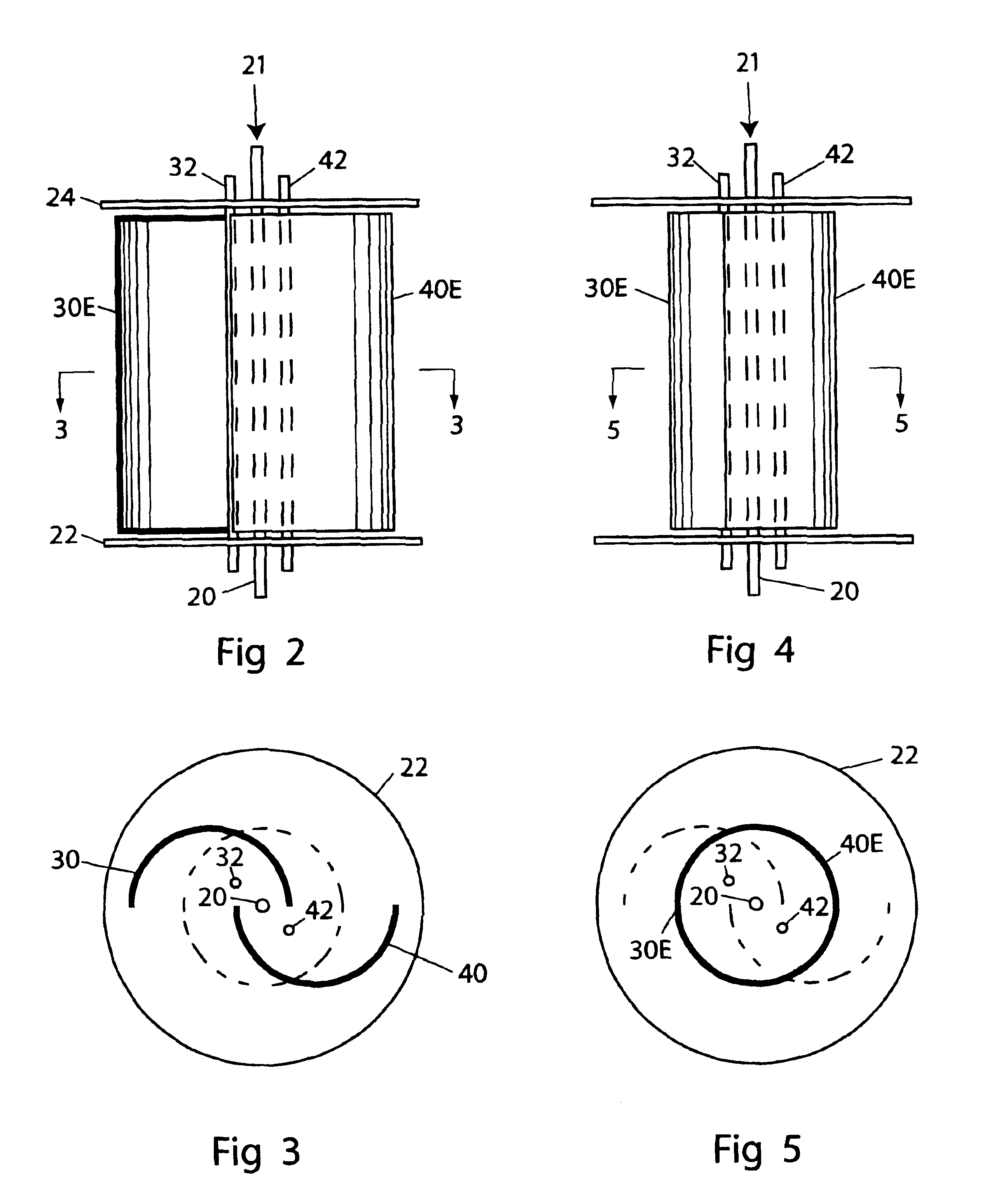
[0054]In FIG. 1 a set of cups 30 and 40 are pivotally attached about a central axis 21, such that they form a closed three dimensional shape when rotated into a closed orientation (FIG. 5), and when ...


PUM


Abstract

A machine that is a self regulating rotor with a set of cups or vanes that are pivotally attached about a central axis such that they form a closed three dimensional shape when closed, and when rotated into an open orientation form an S-shaped rotor, when viewed as a horizontal cross section, a cup shaft to which each cup is attached, such that the cup can pivot or rotate from a closed shape to an open S-shaped rotor, end plates through which cup shafts are pivotally supported, a central shaft to which end plates are attached, a rotational energy connecting element attached to the cup shafts, that control rotation of cup shafts, a rotational speed sensor, and a braking device.

Description

BACKGROUND OF THE INVENTION[0001]This invention relates generally to the field of rotors and more specifically to a self regulating rotor.[0002]Rotors, with both horizontally and vertically oriented axis, have been designed as windmills and wind turbines to capture energy from the wind. There is a great need for devices that can generate electricity from the energy in the wind. Windmill generated electricity can be stored in batteries. It can replace the need for communities in the third world to purchase kerosene for lighting. Wind generated electricity can also power ultra-violet water disinfection and purification systems which can give third world countries a source of clean drinking water. Windmill generated electricity is a non-polluting source of electricity, and will continue to find greater use through out the world.[0003]Horizontal axis rotor designs have found greater acceptance than vertical axis rotors for use as windmill generators. Horizontal axis rotor wind mills are...

Claims


Application Information

Patent Timeline
Patent Type & Authority Patents(United States)
IPC IPC(8): B63H3/00B64C11/30B64C11/00B64C11/06F01C1/00F01D7/00F03C2/00F03D1/00F03C4/00F03D3/00F03D7/06H02M
CPCF03D3/005F03D7/06F05B2240/213Y02E10/74F05B2270/327F05B2270/402F05B2270/304
Inventor KALISKI, ARTHUR
Owner KALISKI ARTHUR
Why Eureka
Try Eureka