Silent chain transmission mechanism

a transmission mechanism and chain technology, applied in the direction of driving chains, gearing, hoisting equipment, etc., can solve the problems of noise and vibration in the chain, interference of the meshing surface, and failure of the chain to work properly

Inactive Publication Date: 2005-06-21
TSUBAKIMOTO CHAIN CO
View PDF4 Cites 10 Cited by
  • Summary
  • Abstract
  • Description
  • Claims
  • Application Information

AI Technical Summary

Benefits of technology

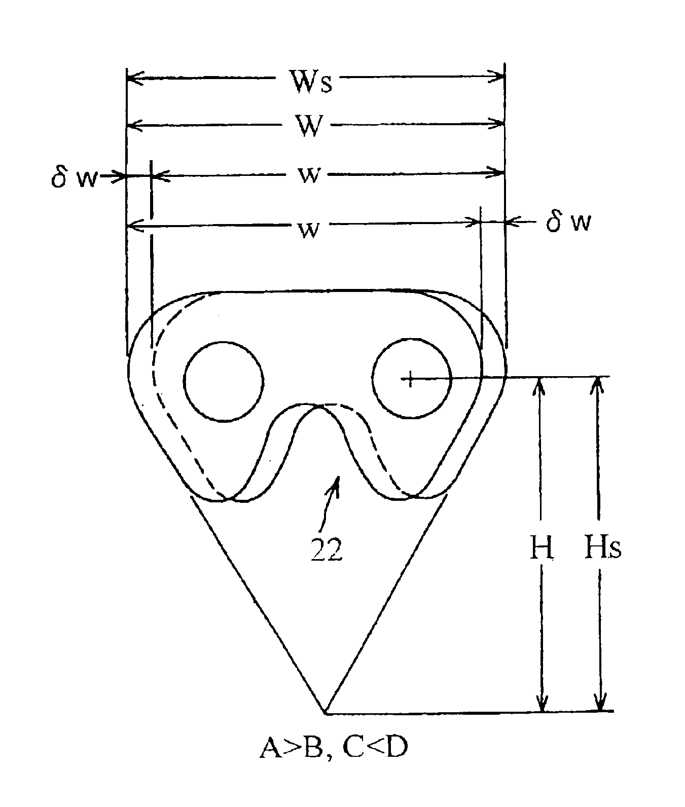
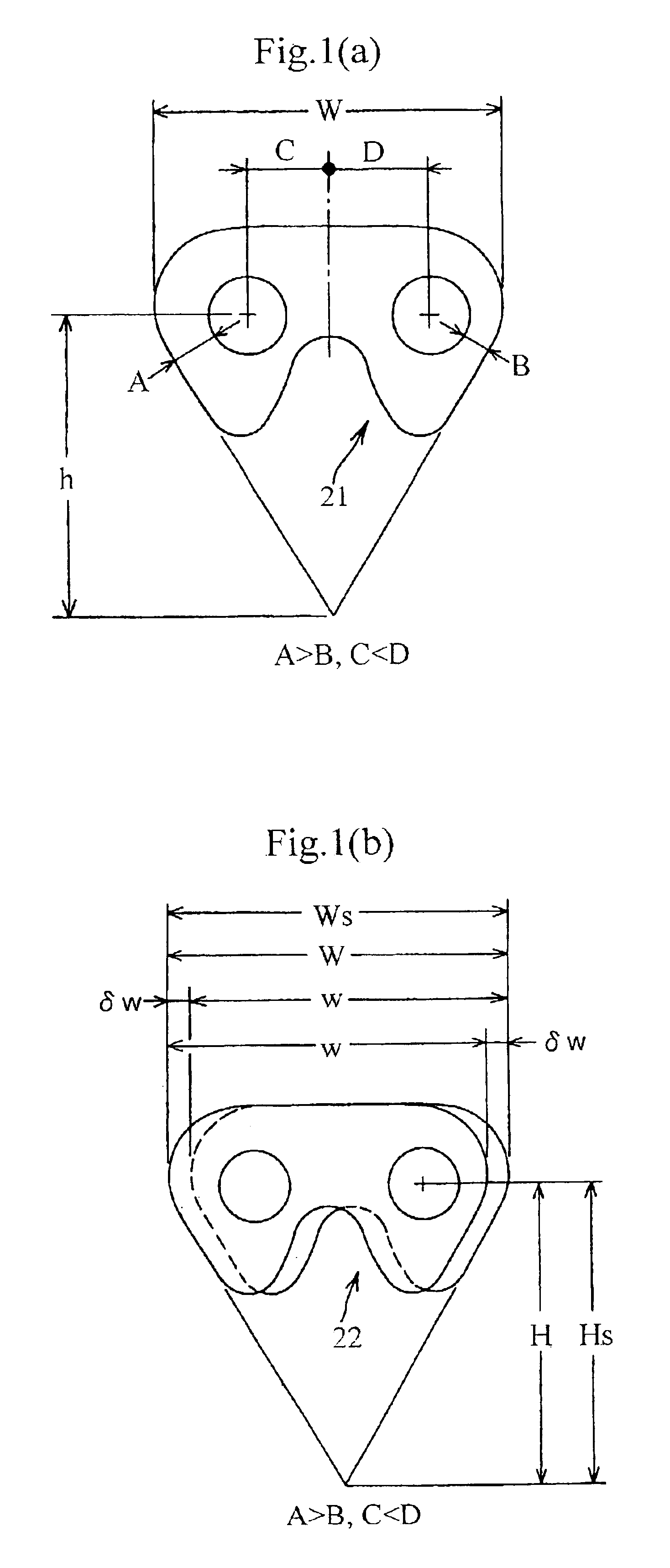
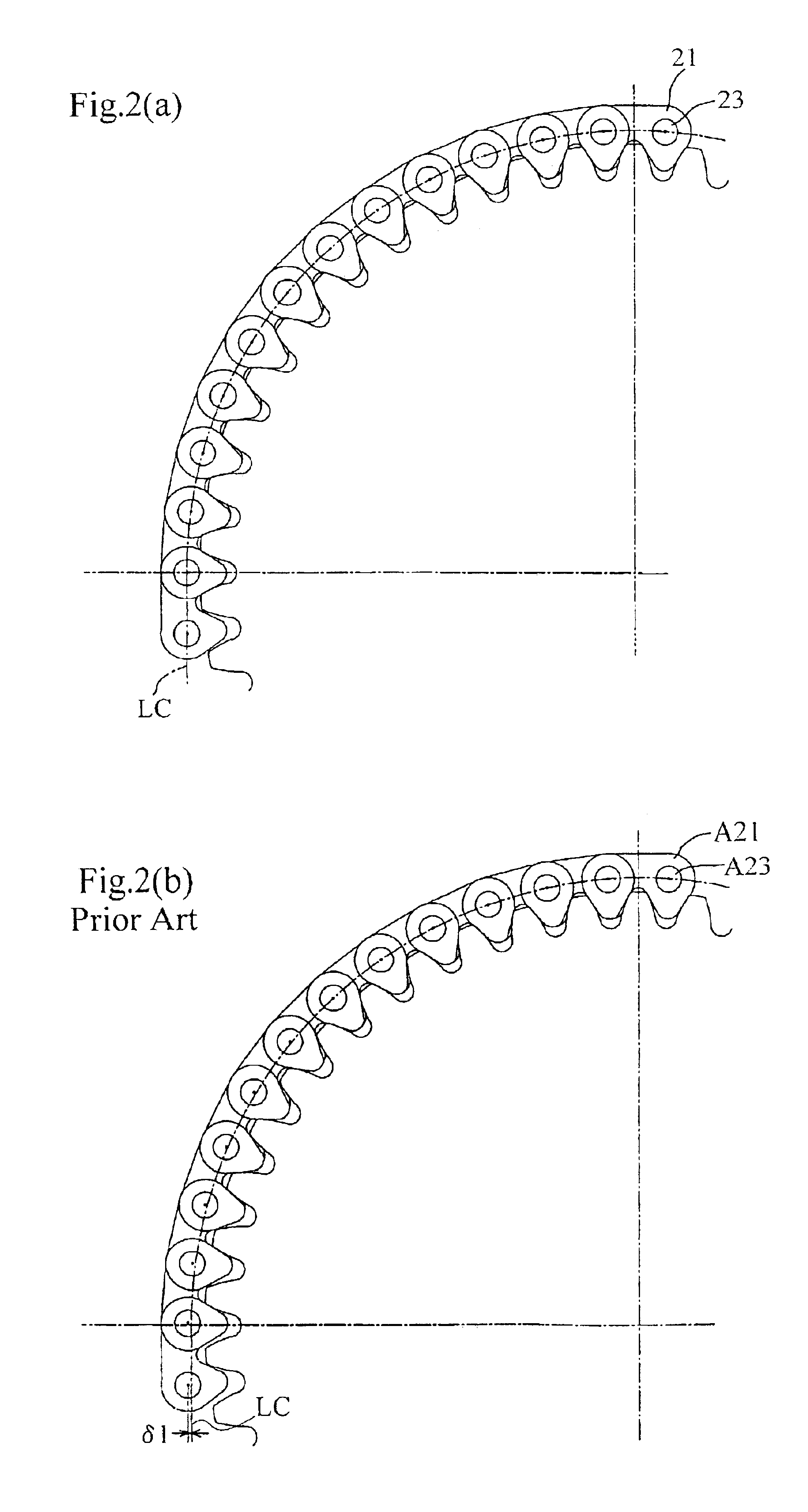
[0012]The silent chain transmission mechanism in accordance with the invention comprises a silent chain and a sprocket. The silent chain is composed of interleaved link rows connected to one another by connecting pins, each link row being composed of plural, toothed, link plates arranged in side-by-side, parallel, relationship. The silent chain is in meshing relationship with the sprocket, and outside meshing surfaces of link rows along a portion of the chain are in seated relationship with teeth of the sprocket. Each link plate has a pair of pin-receiving holes for receiving connecting pins, a pair of teeth having straight, converging, outer flanks, a maximum length w, measured in the direction of the length of the chain, and a height h equal to the distance from a pitch line intersecting the centers of said pin-receiving holes to a point at which imaginary extension lines aligned with the outer flanks intersect. Each link row has a length W equal to the maximum length of a lateral projection of the link row, and a height H equal to the distance from a pitch line intersecting the centers of the pin-receiving holes of the link plates of the link row to a point at which imaginary extension lines aligned with the foremost and rearmost flanks of the link plates in said link row intersect. The link plates of each of link row are gathered at random. The distances from the centers of the pin-receiving holes to the adjacent flanks of a link plate in each row differ from the corresponding distances in a least one other link plate in the same row, and the distances from the centers of the pin-receiving holes to a midline located midway along the length of a link plate in each row differ from the corresponding distances in at least one other link plate in the same row. Consequently the length W and height H of each link row exceed the length w and height h, respectively, of each of the individual link plates in the same link row. Design reference dimensions Ws and Hs, used with reference to a sprocket, are the outside reference dimensions of an ideal link plate such that the meshing surfaces of a chain composed of such ideal link plates finally mesh with, and become seated on, the sprocket teeth during power-transmitting operation of the silent chain with the chain pitch line coinciding with the traveling line. In the chain in accordance with the invention, the length W and the height H of each link row respectively match the design reference length Ws and design reference height Hs for the sprocket, for proper meshing of the chain with the sprocket. Consequently, the chain can properly mesh with the sprocket even when the link plates in each link row are not matched with one another, and even if the link plates in each link row are asymmetric with respect to a center line extending along the longitudinal direction of the chain.

Problems solved by technology

Accordingly, meshing failure can occur even where the chain is engaged with a sprocket designed for optimum engagement and produced using a hob cutter having a hob pitch the same as the chain pitch measured between a pair of pin holes punched in the link plates of the chain.
The differences between the dimensions W and H on the one hand, and the dimensions w and h on the other, leads to problems of noise and vibration in the chain, and also to meshing interference at the meshing surfaces.
Thus, the dimensional differences decrease the resistance of the silent chain to wear.
It is very difficult to attain optimum meshing between the chain and these sprockets across the board, and impossible to avoid meshing failure, which can occur at any one of the sprockets.
Meshing failure leads to a further increase in vibration noise and wear.
This leads to problems that affect noise properties, vibration properties, friction properties, traveling stability and the like.

Method used


Image

  • Silent chain transmission mechanism
  • Silent chain transmission mechanism
  • Silent chain transmission mechanism

Examples


Embodiment Construction

[0020]A preferred embodiment of a silent chain transmission mechanism according to the invention will be described below with reference to the drawings.

[0021]The configuration of the silent chain transmission mechanism in accordance with the invention, when incorporated into a four-cycle engine, is essentially the same as that of the silent chain transmission mechanism shown in FIG. 4. It comprises a valve timing transmission mechanism M1, which transmits power from a valve driving crankshaft sprocket 11a, through valve driving timing silent chain 20a, to an intake valve camshaft sprocket 12a and an exhaust valve camshaft 12b, in order to rotate the intake valve and exhaust valve camshafts once for every two rotations of the crankshaft. The silent chain transmission mechanism also includes a balancer transmission mechanism M2, which transmits power from a balancer driving crankshaft sprocket 11b, through a balancer driving silent chain 20b, to a balancer shaft sprocket, which rotate...


PUM


Abstract

A silent chain transmission mechanism includes a sprocket and a silent chain having link interleaved link rows each composed of plural randomly selected link plates and connected together by connecting pins. The outside dimensions of the link plate are smaller than the outside dimensions of a link, but the outside dimensions of the link match the design reference dimensions of a link plate capable of proper meshing with the sprocket. The requirement for manufacturing accuracy and the effort required for assembly of the silent chain are reduced. However, the silent chain travels on the sprocket on the chain traveling line so that improved noise, vibration and friction properties, and traveling stability are realized.

Description

FIELD OF THE INVENTION[0001]This invention relates to a transmission mechanism, which transmits power between a silent chain and a sprocket, and more specifically to a silent chain transmission mechanism of the kind suitable for driving a camshaft and a balancer shaft from the crankshaft of a four-cycle engine.BACKGROUND OF THE INVENTION[0002]A silent chain transmission mechanism, used to operate intake and exhaust valves, as well as a balancer or other mechanism, from the crankshaft of a four-cycle engine is shown in FIG. 4. The transmission includes a valve timing transmission mechanism M1 comprising a valve-driving crankshaft sprocket A11a, a camshaft sprocket A12a for the intake valves, a camshaft sprocket A12b for the exhaust valves, an endless, valve timing, silent chain 20a, in engagement with the sprockets, and a tensioner 30a, which maintains tension in the chain 20a. The transmission also includes a balancer transmission mechanism M2, comprising a balancer driving cranksha...

Claims


Application Information

Patent Timeline
IPC IPC(8): F16G13/04F16G13/00F16H55/30F16H55/02F16G13/06
CPCF16G13/04F16H55/30
Inventor SAITOH, TOYONAGA
Owner TSUBAKIMOTO CHAIN CO
Why Eureka
Try Eureka