
Method and apparatus for detecting faults in IP packet communication

a packet communication and fault technology, applied in the field of packet communication apparatus, can solve the problems of inability to realize fault monitoring functions, inability to detect performance degradation of transmission paths, and inability to overhead apply, so as to increase the capacity of transmission paths required for ip networks, increase traffic, and increase the need for data communications

Inactive Publication Date: 2005-06-14
HITACHI LTD
View PDF31 Cites 26 Cited by
  • Summary
  • Abstract
  • Description
  • Claims
  • Application Information

AI Technical Summary

Benefits of technology

The patent text discusses the need for a maintenance function of a transmission path in optical networks, especially in the case of IP traffic. The text introduces an operation / maintenance function for monitoring a transmission path in the packet layer, which can be applied to both IP over WDM and IP over Wavelength Division Multiplexing (WDM) networks. The operation / maintenance function can detect and isolate faults in the transmission path, allowing for quick recovery and avoiding degraded performance. The technical effect of this patent is to provide a reliable and efficient maintenance function for optical networks carrying IP traffic.

Problems solved by technology

Furthermore, when such an SDH system is introduced, the overhead such as the section overhead must be applied.
Also, since the bit error of the transmission path can be detected by the BIP function (B1, B2), the performance degradation of the transmission path can be detected.
However, it is practically difficult to realize the fault monitoring function such as monitoring of performance degradation based on the bit error on the transmission path.
As a consequence, if the performance degradation fault could not be detected, then the fault location avoiding operation based on this fault detection cannot be carried out.
As a consequence, these layers own the following technical problems.

Method used


Image

  • Method and apparatus for detecting faults in IP packet communication
  • Method and apparatus for detecting faults in IP packet communication
  • Method and apparatus for detecting faults in IP packet communication

Examples


Embodiment Construction

[0037]Referring now to drawings, an embodiment of the present invention will be described.

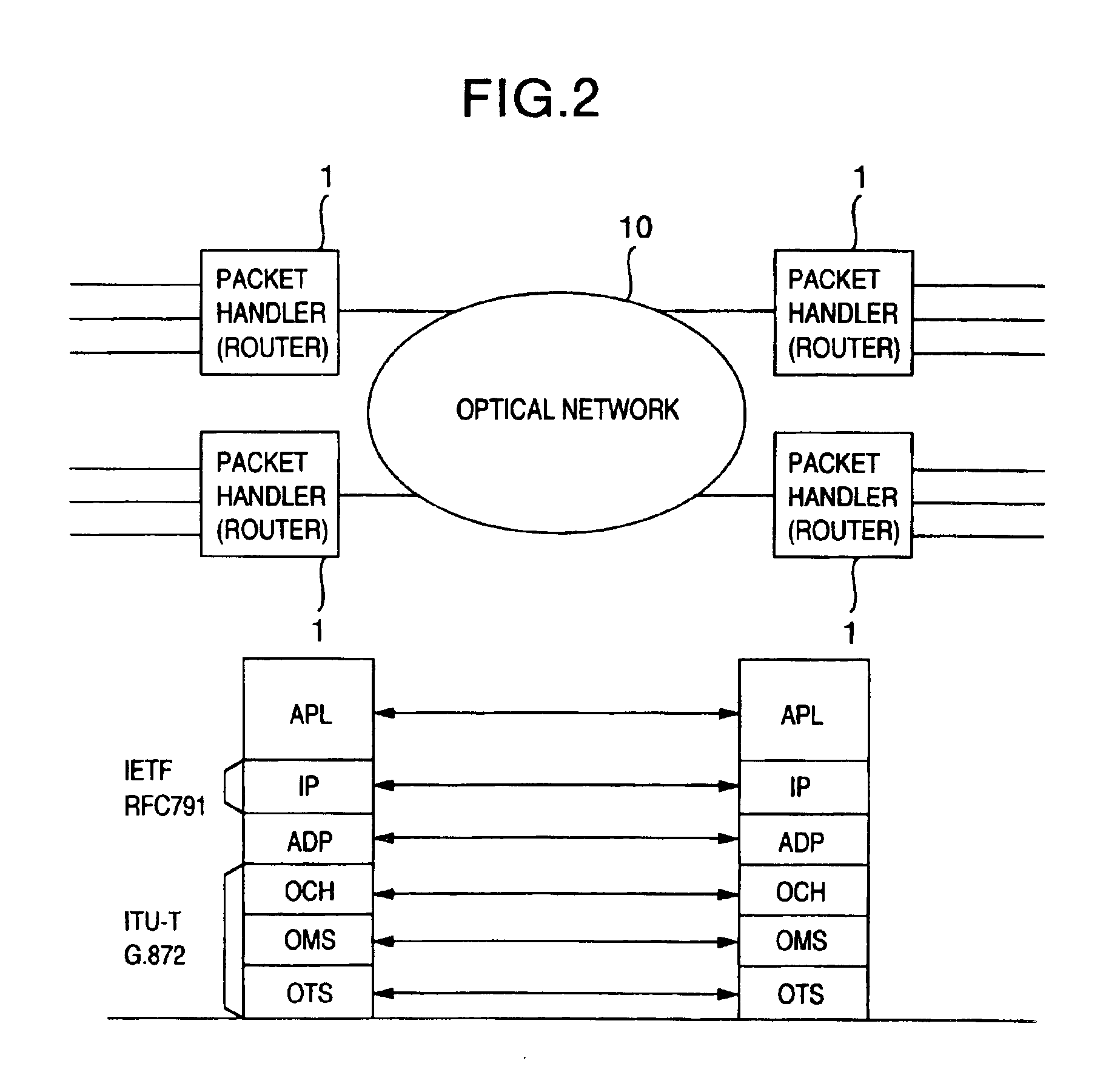
[0038]FIG. 2 represents a network structure containing an optical network 10 to which a packet handler 1 according to the present invention, and a protocol stack to which the present invention is applied, according to an embodiment of the present invention. The packet handler is connected via an optical interface to an optical network.

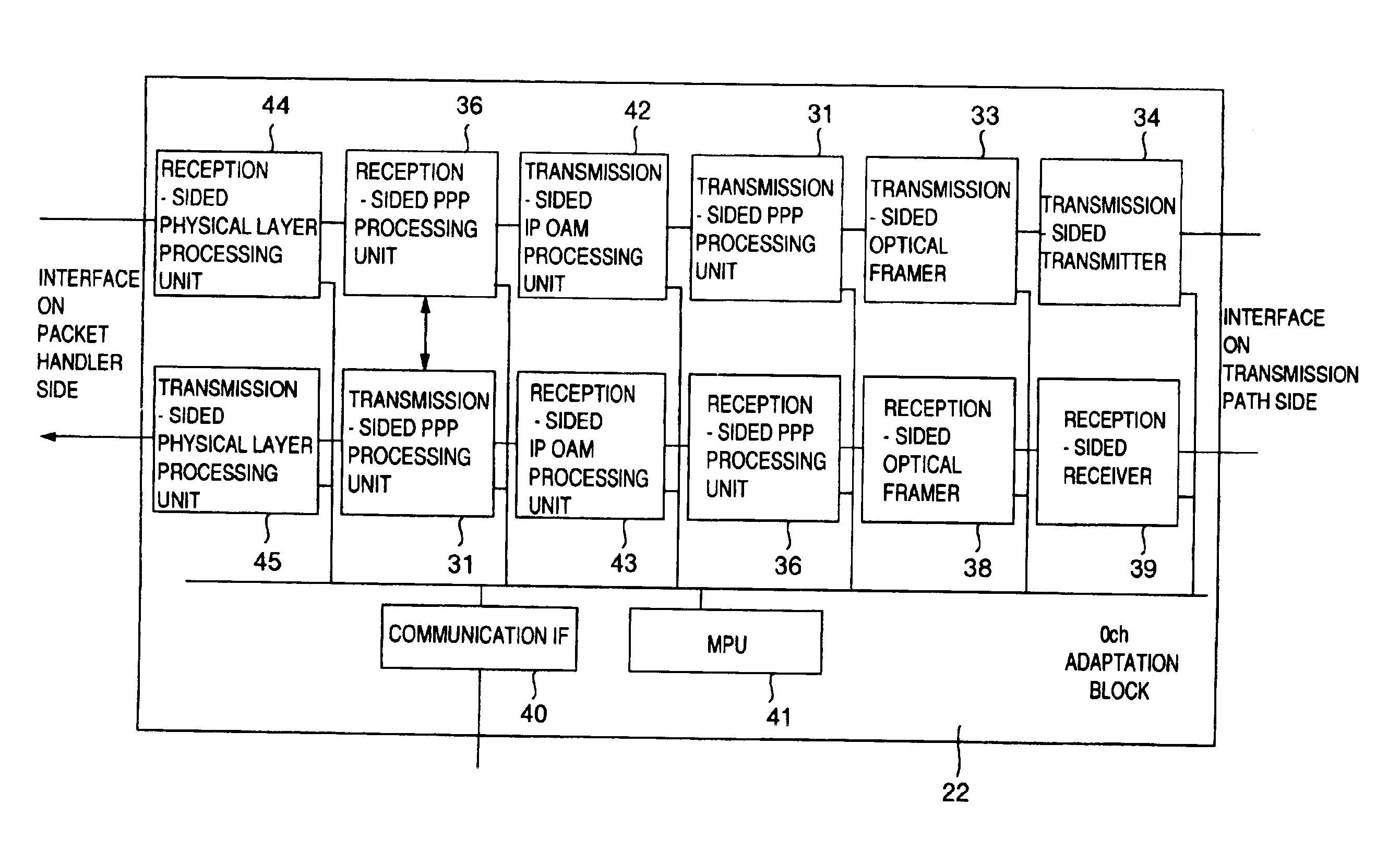
[0039]A structure of the protocol stack is indicated. An IP (Internet Protocol) layer is defined by RFC 791 of IETF (Internet Engineering Task Force) Also, as to an optical network layer, for instance, the protocol stack defined by ITU-T G.872 is employed. An adaptation function involving such a function capable of identifying a head of a packet is required between a packet layer (concretely speaking, IP layer) and the optical network layer (concretely speaking, optical channel layer shown in the drawings). As the adaptation function, for example, PPP (Point-To-Po...


PUM


Abstract

In an IP packet communication apparatus, an operation and maintenance function capable of monitoring a transmission path is provided to a layer used to process a packet, which corresponds to an upper layer of an optical network. As one method for applying the operation and maintenance function to the packet layer, in the case of IP over PPP over WDM, an operation / maintenance frame is defined to a PPP frame so as to realize the operation / maintenance function of a PPP connection. In the case that a plurality of connections are multiplexed on the same transmission path, a maintenance frame is conducted in order to operate / manage these connections by being grouped, so that a fault occurring in the optical network is monitored. As another method for applying the operation and maintenance function to the packet layer, an operation / maintenance frame is defined to an IP packet so as to realize an operation and maintenance function of an IP flow. Also, since a plurality of flows are multiplexed on the same transmission path, a management packet is defined to operate / manage these flows to be grouped, so that a fault occurring in the optical network is monitored.

Description

BACKGROUND OF THE INVENTION[0001]1. Field of the Invention[0002]The present invention is related to a packet communication apparatus.[0003]2. Description of the Related Art[0004]In public communication networks and bank communication networks, since high reliability is required, various operation and maintenance requirements are satisfied. For instance, conditions of communication paths must be monitored, fault states must be immediately detected, and fault location must be avoided. The presently available public transmission networks have conducted the SDH (Synchronous Digital Hierarchy, or, known as “SONET” in the North America) system. This SDH system is normally defined by ITU-T recommendation G.707 (see International Telecommunication Union Telecommunication Standardization Sector). The SDH system may provide these OAM (Operation And Maintenance) functions (in particular, refer to 9.2.2 SOH bytes description of Recommendation G.707). In this SDH system, a header called a sectio...

Claims


Application Information

Patent Timeline
Patent Type & Authority Patents(United States)
IPC IPC(8): H04L12/26H04J14/02H04L12/56H04L69/40
CPCH04J14/0294H04J14/0295H04J14/0241H04L12/2602H04L43/00H04J14/0227H04J14/0278H04J14/0283H04J14/029H04L43/0829H04L43/0847H04L43/10H04L43/16H04J14/0297H04L69/168
Inventor SAKAMOTO, KENICHIENDO, NOBORUSUGAWARA, TOSHIKIWAKAYAMA, KOJIHOSHINO, KAZUYOSHI
Owner HITACHI LTD
Learn More