
Low-k dielectric layer with air gaps

Inactive Publication Date: 2005-06-07
INFINEON TECH LLC
View PDF4 Cites 13 Cited by
  • Summary
  • Abstract
  • Description
  • Claims
  • Application Information

AI Technical Summary

Benefits of technology

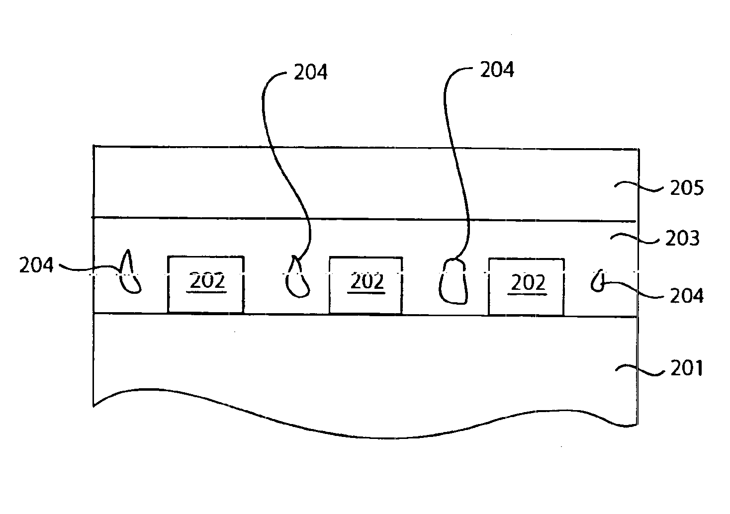
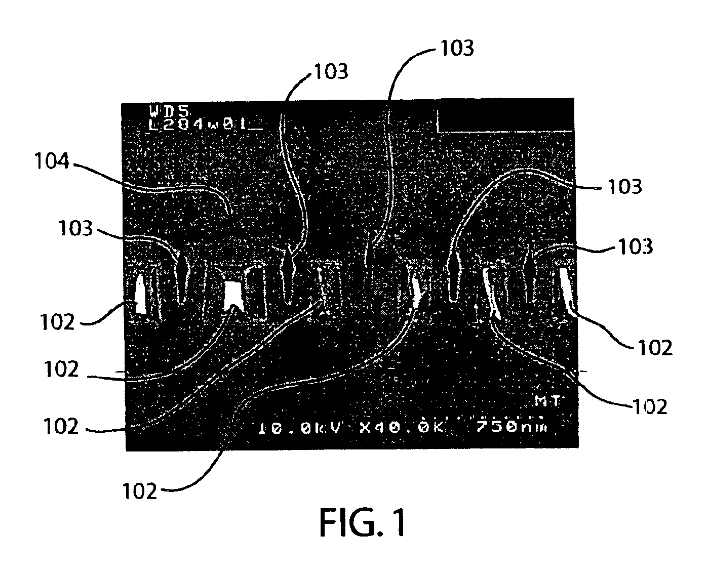
[0005]In one embodiment, a metal level includes a plurality of metal lines. A low-k dielectric is deposited over the metal level such that an air gap forms at least between two metal lines. The relatively low dielectric constant of the low-k dielectric reduces capacitance on metal lines regardless of whether an air gap forms or not. The air gap in the low-k dielectric further reduces capacitance on metal lines. The reduced capacitance translates to lower RC delay and faster signal propagation speeds.

Problems solved by technology

The speed at which a signal is propagated in an integrated circuit is limited by the delay through the metal line carrying the signal.

Method used


Image

  • Low-k dielectric layer with air gaps
  • Low-k dielectric layer with air gaps
  • Low-k dielectric layer with air gaps

Examples


Embodiment Construction

[0012]In the present disclosure, numerous specific details are provided such as examples of materials, process steps, and structures to provide a thorough understanding of embodiments of the invention. Persons of ordinary skill in the art will recognize, however, that the invention can be practiced without one or more of the specific details. In other instances, well-known details are not shown or described to avoid obscuring aspects of the invention.

[0013]The present invention relates to methods and associated structures for lowering the RC delay of metal lines in integrated circuits. The resistance of a metal line, and hence its RC delay, may be lowered by using a low resistance material such as copper to form the metal line. To reduce capacitance, so-called low-k dielectrics may be deposited between metal lines. A low-k dielectric is a dielectric material that has relatively low dielectric constant. Commercially available low-k dielectrics have a dielectric constant less than or ...


PUM


Abstract

In one embodiment, a metal level includes a plurality of metal lines. A low-k dielectric is deposited over the metal level such that an air gap forms at least between two metal lines. The relatively low dielectric constant of the low-k dielectric reduces capacitance on metal lines regardless of whether an air gap forms or not. The air gap in the low-k dielectric further reduces capacitance on metal lines. The reduced capacitance translates to lower RC delay and faster signal propagation speeds.

Description

BACKGROUND OF THE INVENTION[0001]1. Field of the Invention[0002]The present invention relates generally to integrated circuits, and more particularly to integrated circuit fabrication processes and structures.[0003]2. Description of the Background Art[0004]The speed at which a signal is propagated in an integrated circuit is limited by the delay through the metal line carrying the signal. This delay, commonly known as “RC delay,” is determined by the product of the resistance (R) and capacitance (C) of the metal line. Reducing the resistance and / or capacitance of a metal line lowers its RC delay and increases signal propagation speed. Thus, reducing the RC delay of metal lines plays a major role in making integrated circuits run faster.SUMMARY[0005]In one embodiment, a metal level includes a plurality of metal lines. A low-k dielectric is deposited over the metal level such that an air gap forms at least between two metal lines. The relatively low dielectric constant of the low-k di...

Claims


Application Information

Patent Timeline
IPC IPC(8): H01L21/02H01L21/4763H01L21/302H01L21/768
CPCH01L21/7682
Inventor BEN-TZUR, MIRARAMKUMAR, KRISHNASWAMYSEAMS, CHRISTOPHER A.RODGERS, THURMAN J.
Owner INFINEON TECH LLC
Learn More