Hydrogen removing apparatus
a technology removing apparatus, which is applied in the direction of physical/chemical process catalysts, greenhouse gas reduction, separation processes, etc., can solve the problems of difficult hydrogen gas removal, low oxygen gas concentration, and only about several percent of the alloy weight of hydrogen absorbing alloy, etc., to suppress the elevation of pressure within the closed space
- Summary
- Abstract
- Description
- Claims
- Application Information
AI Technical Summary
Benefits of technology
Problems solved by technology
Method used
Image
Examples
example 1
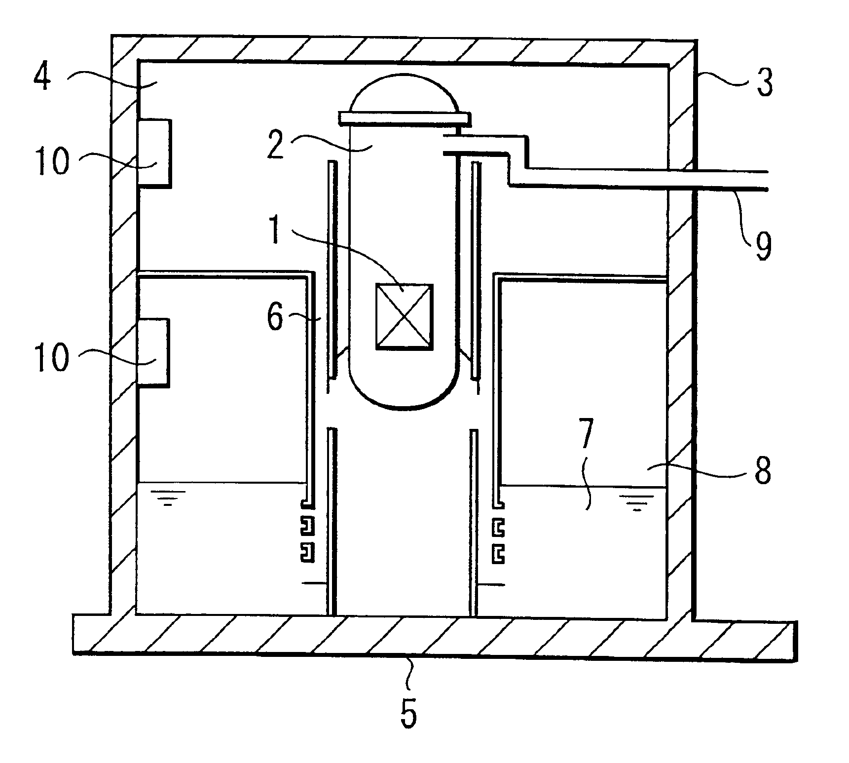
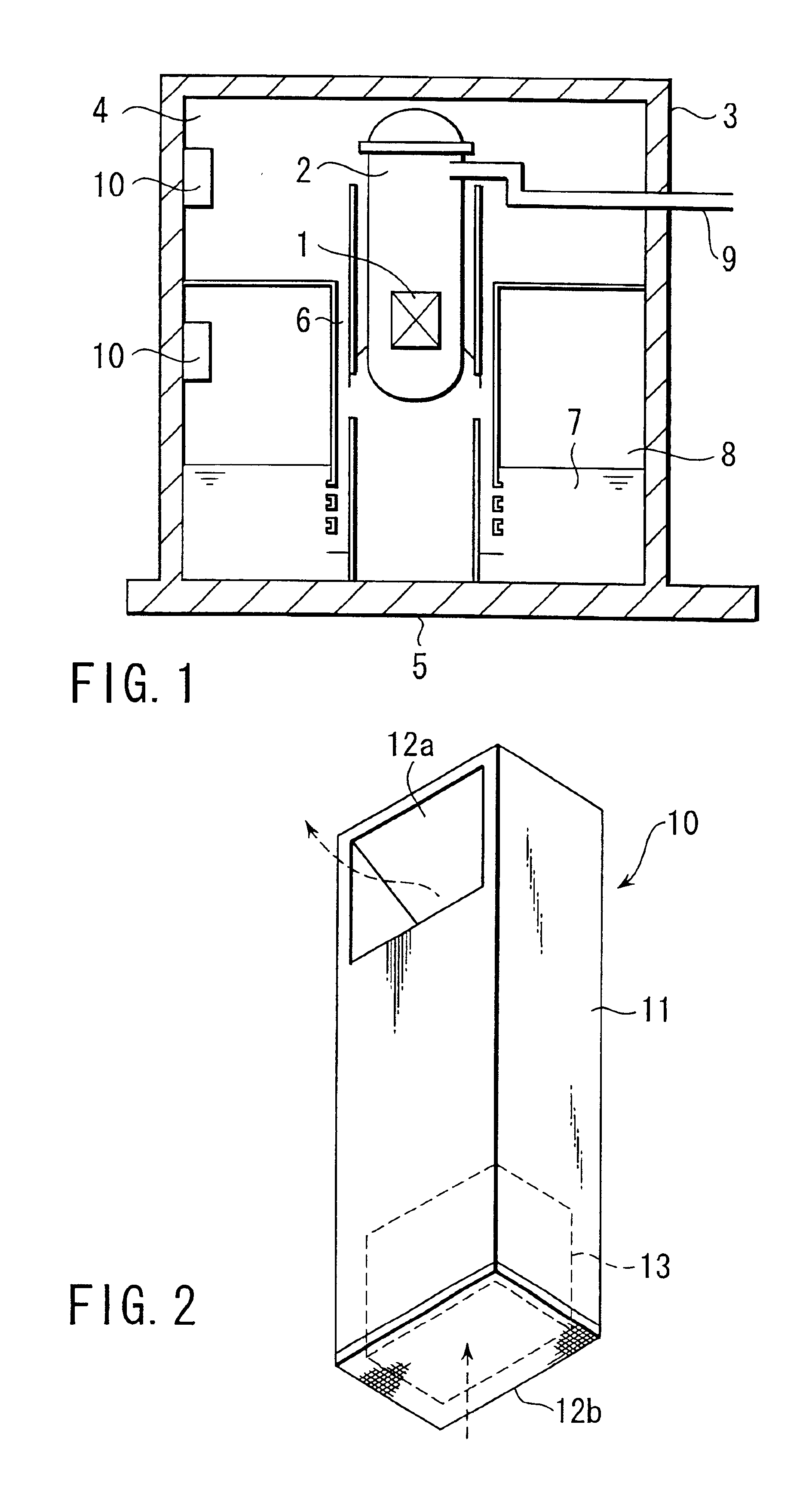
[0049]FIG. 1 is a cross sectional view schematically showing a nuclear reactor-housing vessel in which is housed a hydrogen removing apparatus of Example 1, and FIG. 2 is an oblique view showing the hydrogen removing apparatus housed in the nuclear reactor-housing vessel shown in FIG. 1.
[0050]As shown in the drawings, a nuclear reactor pressure vessel 2 housing a nuclear reactor core 1 is housed in a nuclear reactor-housing vessel 3. The nuclear reactor-housing vessel 3 is filled with a nitrogen gas by exchanging an air for the nitrogen gas. The nuclear reactor-housing vessel 3 comprises an upper dry well 4 surrounding the nuclear reactor pressure vessel 2, a lower dry well 5, and a wet well 8 communicating with the upper dry well 4 via a vent pipe 6 and having a suppression pool 7 arranged therein. A nuclear reactor primary cooling pipe such as a main steam pipe 9 is connected to the nuclear reactor pressure vessel 2. Two hydrogen removing apparatus 10 are mounted in portions of th...
example 2
[0077]Example 2 is directed to a suitable shape of the catalyst bed used in the hydrogen removing apparatus of Example 1 described above.
[0078]Specifically, FIG. 7A is an oblique view showing a cartridge type catalyst bed 13 used in the hydrogen removing apparatus of Example 2, which is arranged within a nuclear reactor-housing vessel, and FIG. 7B is an oblique view showing the cartridge 14 constituting the catalyst bed shown in FIG. 7A.
[0079]Catalysts 15 molded in a granular shape are loaded in the plate-like cartridge 15. The catalyst bed 13, which is arranged within the reactor 11 shown in FIG. 2, is formed by arranging a plurality cartridges 14 a desired distance apart from each other. It should be noted that the clearance between adjacent cartridges 14 provides a gas passageway substantially perpendicular to the bottom surface of the reactor 11.
[0080]The surface layer of the cartridge 14 is formed of a porous material or a mesh-like material such that the gaseous materials with...
example 3
[0084]Example 3 is directed to another preferred shape of the catalyst bed used in the hydrogen removing apparatus of Example 1.
[0085]Specifically, FIG. 8 is an oblique view showing a catalyst bed 13 of Example 3, which is used in a hydrogen removing apparatus arranged in a nuclear reactor-housing vessel.
[0086]As shown in the drawing, the catalyst bed 13 is formed by loading catalyst particles 15 molded in a granular shape in a cylindrical cartridge 16. Gas circulating sections 17a, 17b, which are in the form of, for example, a mesh, are formed in the top portion and the bottom portion, respectively, of the cylindrical cartridge 16. It is possible to use a porous material for forming the gas circulating sections 17a, 17b. The catalyst bed 13 of the particular construction is housed in the reactor 11 shown in FIG. 2, and the gaseous materials within the reactor are circulated into the cartridge 16 through the gas circulating sections 17a, 17b.
[0087]According to Example 3, the cataly...
PUM
| Property | Measurement | Unit |
|---|---|---|
| Percent by mass | aaaaa | aaaaa |
| Percent by mass | aaaaa | aaaaa |
| Specific surface area | aaaaa | aaaaa |
Abstract
Description
Claims
Application Information
 - R&D
- Intellectual Property
- Life Sciences
- Materials
- Tech Scout
- Unparalleled Data Quality
- Higher Quality Content
- 60% Fewer Hallucinations
Browse by: Latest US Patents, China's latest patents, Technical Efficacy Thesaurus, Application Domain, Technology Topic, Popular Technical Reports.
© 2025 PatSnap. All rights reserved.Legal|Privacy policy|Modern Slavery Act Transparency Statement|Sitemap|About US| Contact US: help@patsnap.com


