
Drill insert with controlled contact clearance

a technology of contact clearance and drill bit, which is applied in the direction of cutting inserts, twist drills, manufacturing tools, etc., can solve the problems of wear on the flank and clearance of cutting inserts

Inactive Publication Date: 2005-06-07
ALLIED MASCH & ENG CORP
View PDF13 Cites 7 Cited by
  • Summary
  • Abstract
  • Description
  • Claims
  • Application Information

AI Technical Summary

Benefits of technology

[0004]The present invention provides a novel drill insert having a controlled contact clearance formed behind the cutting edges. The controlled contact clearance limits flank wear and enables more coolant near the cutting edge. These and other advantages are provided by a drill insert comprising: a drill insert body having a cutting edge; a clearance surface formed on a trailing side of the cutting edge; an undercut formed in the clearance surface at a predetermined distance from the cutting edge and at a predetermined depth in the clearance surface; wherein the remaining clearance surface between the cutting edge and the undercut provides a controlled contact clearance surface limiting the flank wear to substantially the width of the controlled contact clearance surface.

Problems solved by technology

This is especially true of hard to cut, abrasive workpieces which quickly wear the flank and clearance of cutting insert.

Method used


Image

  • Drill insert with controlled contact clearance
  • Drill insert with controlled contact clearance
  • Drill insert with controlled contact clearance

Examples


Embodiment Construction

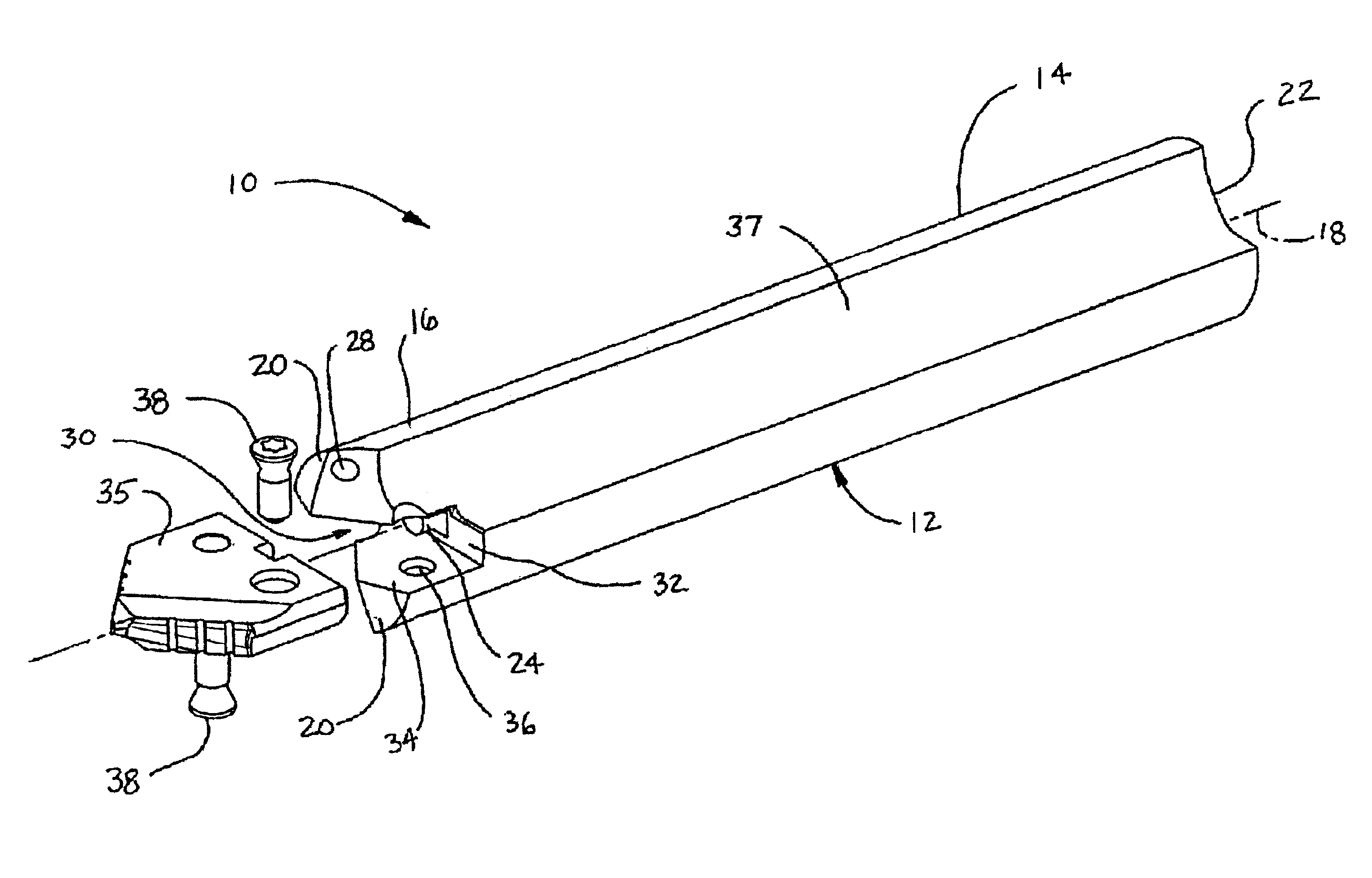
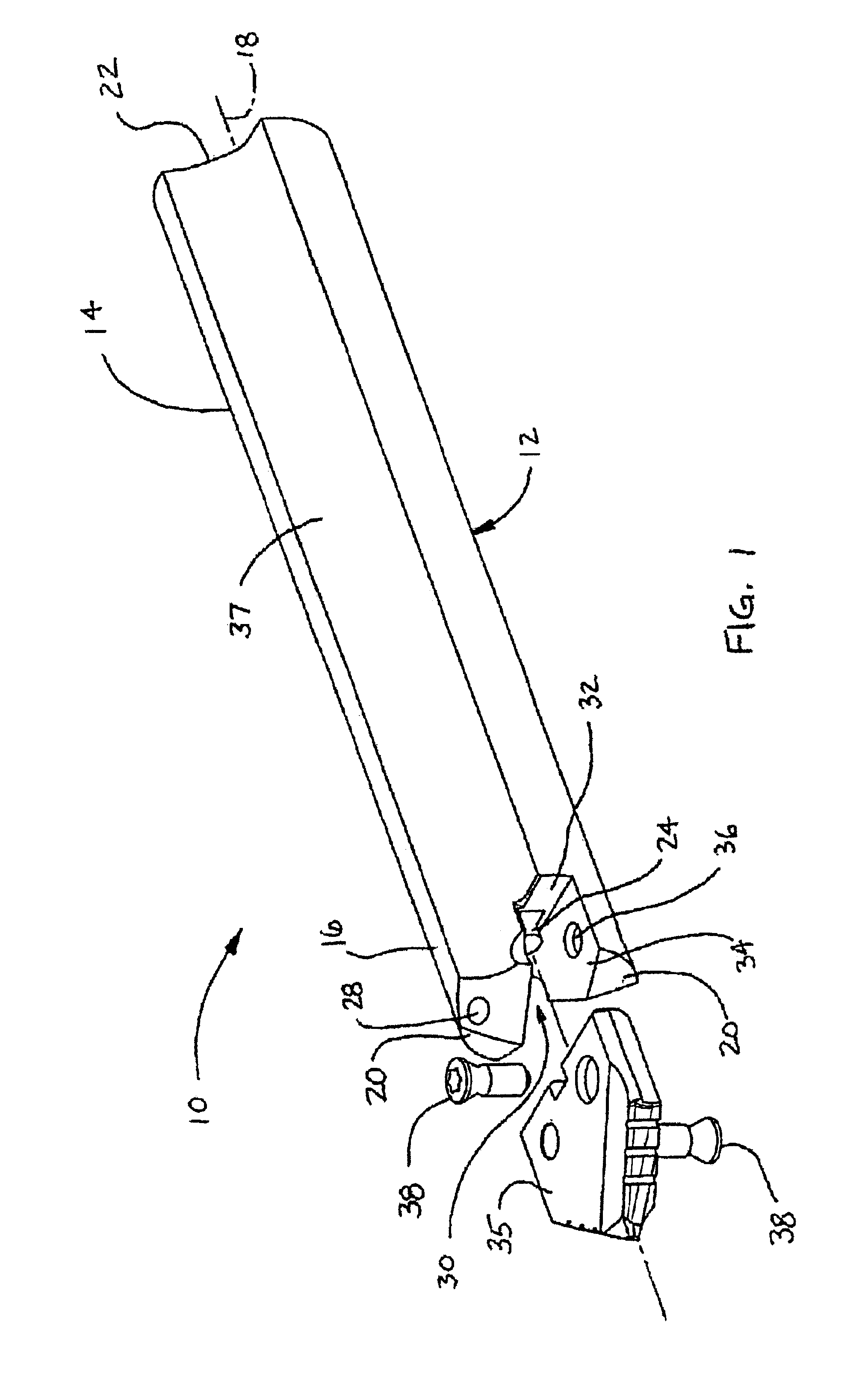
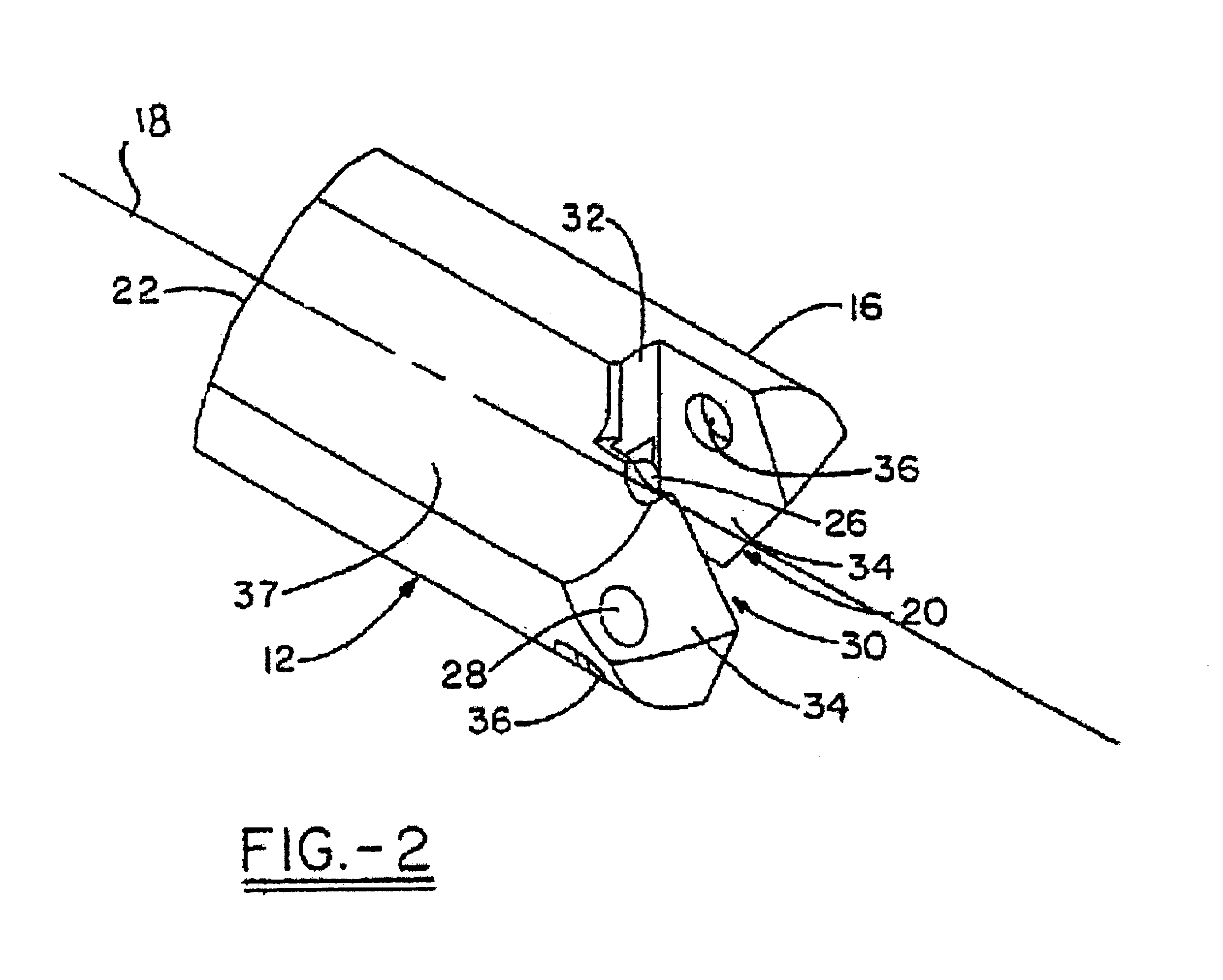
[0016]Turning now to an embodiment of the invention, FIG. 1 illustrates a drill tool assembly 10 generally indicated. Drill tool assembly 10 comprises a holder 12, which has a shank 14 and head portion 16 associated therewith. In one embodiment, holder 12 has, in general, a cylindrical shape with a first end 20 and second end 22, with the second end 22 and a portion of shank 14 adapted to be fixedly attached in a drilling machine for use. The first end 20 of holder 12 has a clamping or holder slot 30, which may extend across the entire diameter of the head portion 16 or, at least, over a center portion thereof at the general location of the rotational axis 18 of holder 12. The holder slot 30 has a bottom wall 32 positioned in substantially perpendicular orientation relative to the rotational axis 18 of the holder 12. In one embodiment, the assembly 10 may further include a locating boss or dowel pin 24, which is positioned precisely with respect to the axis 18 and extends from the b...


PUM

PropertyMeasurementUnit
distanceaaaaaaaaaa
depthaaaaaaaaaa
widthaaaaaaaaaa

Abstract

A cutting tool insert having a controlled contact clearance behind the cutting edge which limits flank wear and allows more coolant near the cutting edge further allowing an increase in surface speed, feed rates, and tool life. The controlled contact clearance surface provides a first wear zone and a second wear zone, the first wear zone generated during operation of the drill insert allows the flank wear distance to grow from zero to the distance from the cutting edge to the controlled contact clearance surface, the second wear zone keeps the flank wear distance substantially constant until the controlled contact clearance surface is substantially worn away.

Description

TECHNICAL FIELD[0001]The invention relates generally to a cutting insert to be placed into a tool holder for boring holes into metals. More specifically the invention relates to a cutting tool insert having a specialized geometry including a controlled contact clearance behind the cutting edge which limits flank wear and allows more coolant near the cutting edge further allowing an increase in surface speed, feed rates, and tool life.BACKGROUND OF THE INVENTION[0002]Drilling systems are frequently used to provide cylindrical holes in metallic workpieces. The cutting or boring action of the drill system may be carried out by an elongated, substantially cylindrical drilling tool, such as a combination of a tool holder and a drill insert, which is selectively attached thereto. Such an arrangement may then be used in an application wherein one end of the tool holder is securely mounted in a driving apparatus, which rotates the holder about its longitudinal axis. At the opposite end of t...

Claims


Application Information

Patent Timeline
Patent Type & Authority Patents(United States)
IPC IPC(8): B23B51/00
CPCB23B51/0009B23B2200/126B23B2251/48B23B2251/50Y10T408/909Y10S408/713Y10T408/9095B23B51/00035
Inventor KRAEMER, ROLF H.
Owner ALLIED MASCH & ENG CORP
Learn More