Sharpening unit and cutting machine comprising at least one blade and said sharpening unit

Inactive Publication Date: 2006-01-19
FABIO PERINI SPA
View PDF7 Cites 13 Cited by
  • Summary
  • Abstract
  • Description
  • Claims
  • Application Information

AI Technical Summary

Benefits of technology

[0017] The object of the present invention is to provide a sharpening unit, in particular although not exclusively for cutting machines to cut elongated products, which allows more efficient sharpening in respect of prior art sharpening units.
[0018] Another object of the invention is to provide a cutting machine to cut products, especially although not exclusively logs of web material, comprising at least one particularly efficient sharpening unit and which on the one hand sharpens the blades accurately and on the other causes limited wear on the blade(s).
[0019] For this object, according to a first aspect of the present invention, a sharpening unit is provided comprising a grinding wheel unit with at least two opposed grinding wheels to act on two sides of a blade, characterized in that said grinding wheel unit is equipped with at least a degree of freedom to center the grinding wheels in respect of a lying surface of the portion of the cutting edge of the blade on which the grinding wheels act This allows a balanced and uniform sharpening action on the two sides of the blade. Moreover, when the grinding wheel unit is equipped with a movement towards the blade to recover any decreases in the dimension of the blade caused by wear, with self-centering of the grinding wheels the pressure exerted can be controlled more accurately, avoiding pressures and thus excessive wear.
[0021] A further aspect of the present invention relates to a cutting machine for cutting elongated products, comprising: at least one path for the products to be cut; at least one device to feed the products along said path; at least one blade provided with a cutting movement to cut said products; at least one sharpening unit for said blade, which comprises a grinding wheel unit with at least two opposed grinding wheels to act on two sides of said blade. According to the invention, the machine is characterized in that the grinding wheel unit is provided with at least a degree of freedom to center the grinding wheels in respect of a lying surface of the portion of the cutting edge, that is of the cutting bevel of the blade on which the grinding wheels act. The grinding wheel unit can be taken to a fixed position in respect of the blade, when the dimensions of the latter vary slightly due to wear and said wear can be recovered for example by moving the grinding wheels towards the blade without also moving the grinding wheel unit. Nonetheless, the sharpening unit normally comprises a system to move the grinding wheel unit towards the blade along a direction of forward movement, to recover wear on the blade. In this case, self-centering of the grinding wheels is particularly important and advantageous as it prevents the onset of excessive sharpening pressures, or—on the contrary—conditions of insufficient pressure and thus insufficient sharpening.
[0022] According to a particular embodiment, the grinding wheel unit is provided with a further degree of freedom, partly restricted, to center the grinding wheels in respect of the blade. Partly restricted degree of freedom is intended as possible movement restricted, for example, through the effect of a return spring and / or an actuator that limits the freedom of movement of the grinding wheel unit according to this degree of freedom. For example, the grinding wheel unit is free to move in one direction, but its movement is limited in the other direction, or the movement is contrasted by a return spring. This guarantees that the movement according to this further degree of freedom always brings the grinding wheels into contact with the blade to be sharpened, preventing movement away from the cutting edge.

Problems solved by technology

This means that there is often more pressure of the grinding wheels on the blade than necessary and consequently also excessive wear on the blade.
On the contrary, there may be insufficient sharpening pressure, caused by the blade and the grinding wheels not having been moved close enough together.
In this case sharpening is not performed efficaciously.
Moreover, due to the rigidity of the grinding wheel unit the pressure with which the two grinding wheels operate on the two sides of the blade is not equal, due to unavoidable errors in positioning, tolerances and any uneven wear on the grinding wheels.

Method used


Image

  • Sharpening unit and cutting machine comprising at least one blade and said sharpening unit
  • Sharpening unit and cutting machine comprising at least one blade and said sharpening unit
  • Sharpening unit and cutting machine comprising at least one blade and said sharpening unit

Examples


Embodiment Construction

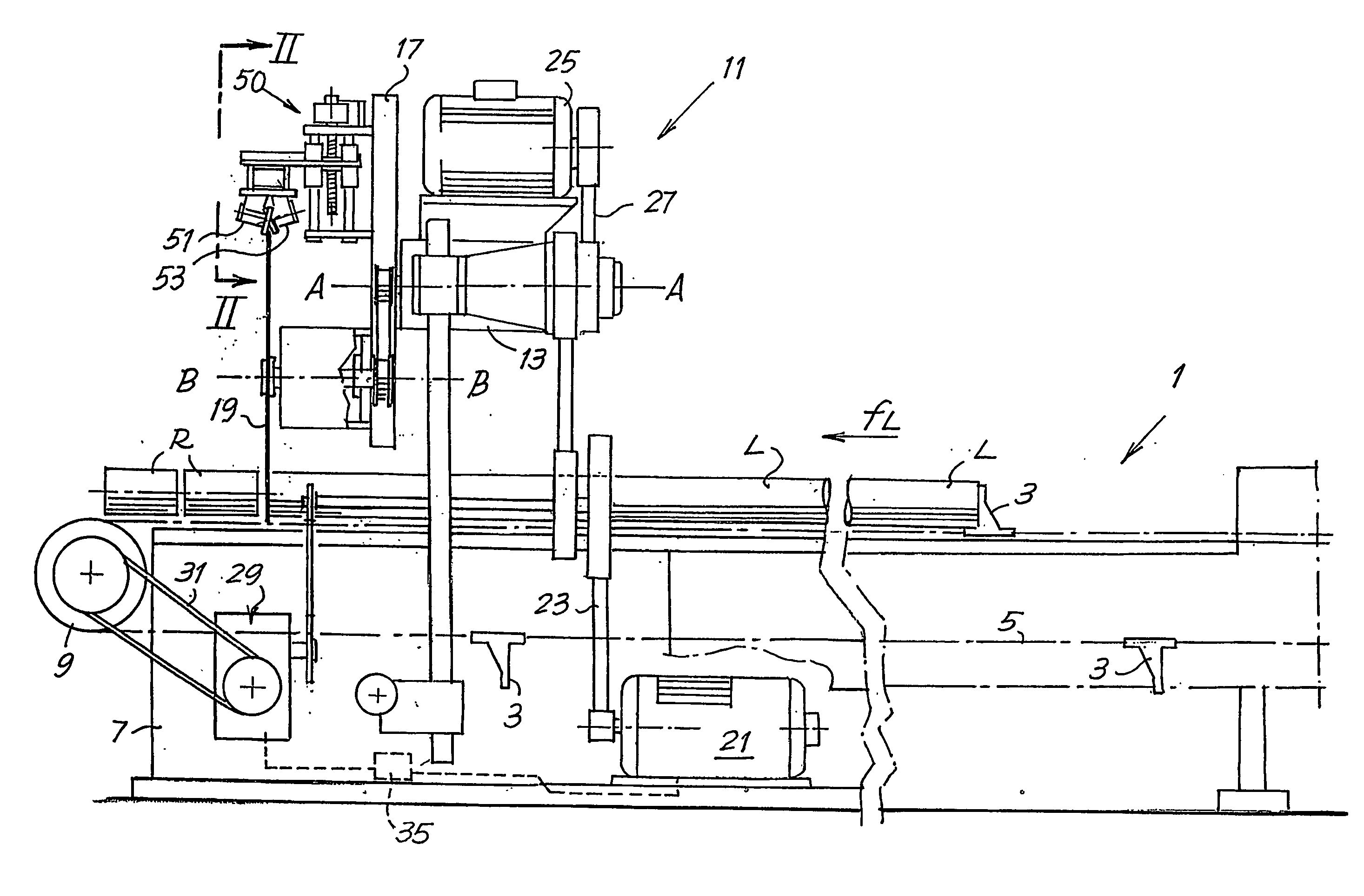
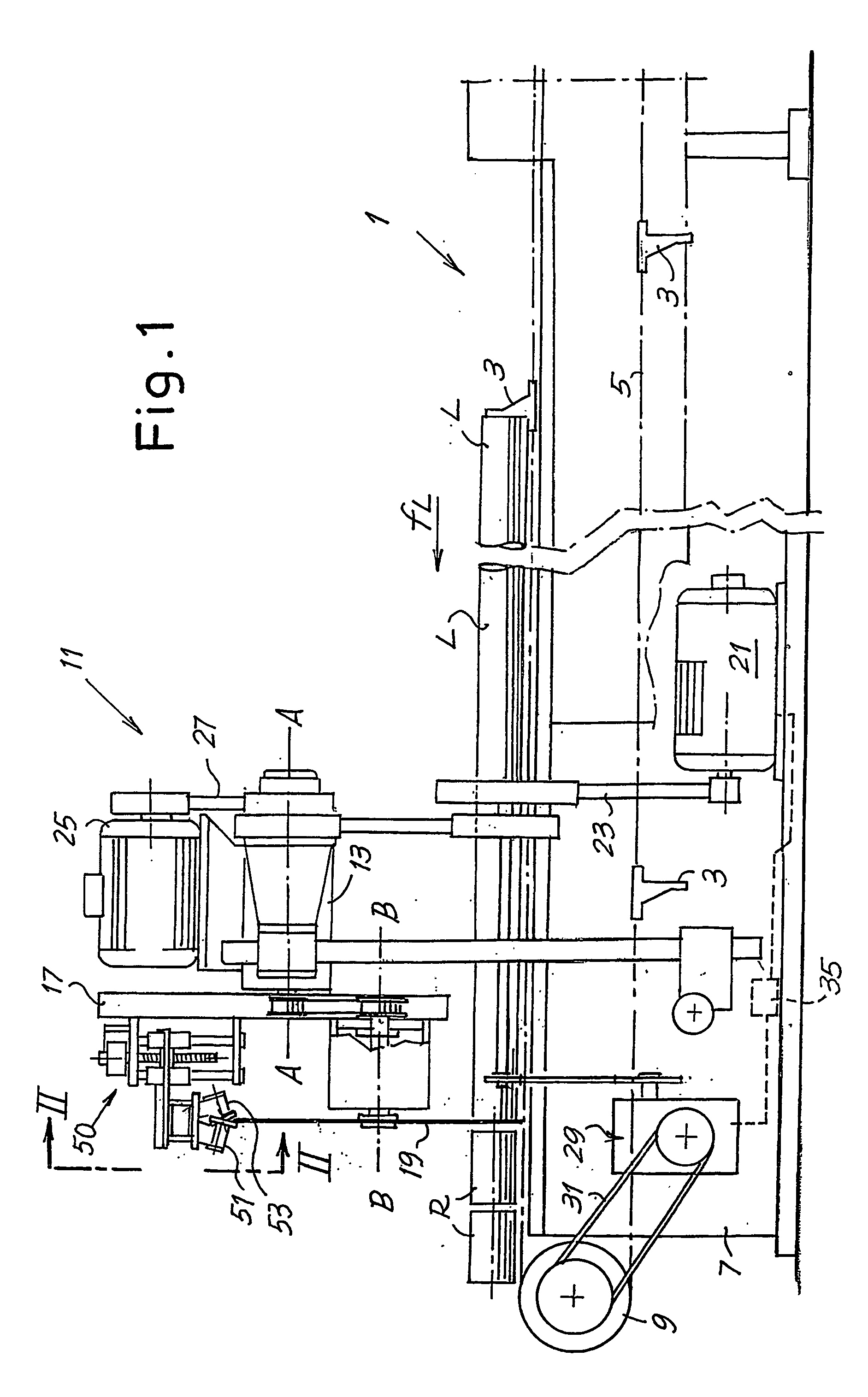
[0038]FIG. 1 schematically shows a cutting machine according to the present invention.

[0039] In this case it is a cutting machine for rolls of paper or other wound web material, wherein the cut is performed by a-disk-shaped blade rotating about its axis, carried by a unit in turn rotating about a principal axis of rotation, parallel or approximately parallel to the direction of feed of the rolls to be cut. Advantageously, a sharpening unit of the type shown in FIGS. 5 to 7 with motorized grinding wheels is applied to a machine of this type.

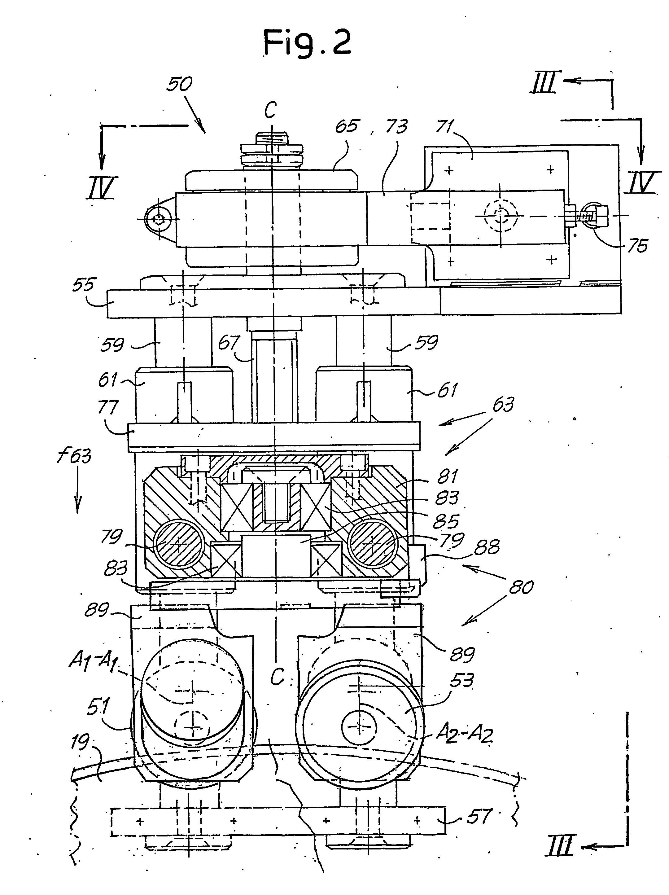
[0040] However, a sharpening unit with idle grinding wheels, of the type shown in FIGS. 2 to 4, may be applied (if need be in combination with or alternatively to it). The sharpening units, which shall be described hereunder with particular reference to FIGS. 2 to 7, may also be applied to different machines, such as cutting machines with a helical blade or with a band blade. It must therefore be understood that the machine shown in FIG. 1 must ...


PUM

PropertyMeasurementUnit
Angleaaaaaaaaaa
Gravityaaaaaaaaaa
Stress optical coefficientaaaaaaaaaa

Abstract

The sharpening unit (50) comprises a grinding wheel unit (80) with at least two grinding wheels (51, 53) opposed to act on two sides defining a cutting bevel of the blade (19). The grinding wheel unit is provided with at least a degree of freedom to center the grinding wheels (51, 53) in respect of a lying surface of the portion of the cutting bevel of the blade (19) on which said grinding wheels act.

Description

DESCRIPTION [0001] 1. Technical Field [0002] The present invention relates to a cutting machine for cutting elongated products, such as and in particular logs of web material for the production of small rolls destined for packaging and sale. [0003] More specifically, the invention relates to a cutting machine with at least a cutting blade and at least a sharpening unit associated with said cutting blade. [0004] The invention also relates to a sharpening unit for cutting machines or other machines provided with a blade that must be constantly or periodically sharpened. [0005] 2. State of the Art [0006] In the paper converting industry rolls or logs of substantial axial length are produced by winding a predetermined quantity of paper, for example tissue paper, to subsequently produce small rolls of toilet tissue, kitchen towels and the like. For this purpose the logs are cut orthogonal to their axis and divided into a plurality of small rolls of a suitable length, which are then packa...

Claims


Application Information

Patent Timeline
IPC IPC(8): B24D15/00B24B3/36B26D7/12
CPCB26D7/12B24B3/368
Inventor CHIOCCHETTI, MARIO GIONIGELLI, MAURORIDOLFI, QUIRINO FERNANDO
Owner FABIO PERINI SPA
Why Eureka
Try Eureka