
Plastics drum for concrete mixing and methods of manufacture thereof

a technology of concrete and plastics, which is applied in the direction of combs, buttons, hollow wall objects, etc., can solve the problems of steel drum internal surfaces being subject to significant wear and tear, eventual wear and tear, and high production costs of steel drums, so as to prolong the life of the drum, improve the concrete mixing characteristics, and increase the concrete carrying capacity of the drum

Inactive Publication Date: 2005-06-07
KHOURI ANTHONY
View PDF38 Cites 29 Cited by
  • Summary
  • Abstract
  • Description
  • Claims
  • Application Information

AI Technical Summary

Benefits of technology

The plastic drum offers improved mixing efficiency, extended lifespan, and increased payload capacity while reducing wear and maintenance costs, outlasting steel drums and maintaining concrete workability in varying temperatures.

Problems solved by technology

While steel drums have been in use for many years, they suffer from a number of attendant disadvantages. relating to their cost of manufacture and replacement, working life, wear characteristics, weight and volume.
Steel drums are expensive to manufacture due to their labour intensive construction which involves rolling steel sheets into conical portions and cylinders which once fabricated are then welded to form the finished tank.
As concrete is a highly abrasive material, internal surfaces of steel drums are subject to significant wear abrasion.
This occurs particularly on the surfaces which take slump impact, sliding friction and shear load leading to eventual wearing out of the drum.
Typically, a steel drum used every day might last three to five years, thereafter requiring replacement at significant cost.
Thus there are ‘dead’ spots in the mix where no mixing takes place and where there is an increased potential for unwanted collection of concrete.
In addition to the above problems associated with the use of steel mixing drums, there are cost and weight factors which add to inherent inefficiencies in use of steel drums.
The drum described in this patent is for light duty operation and does not have the structural and materials characteristics necessary for heavy duty concrete mixing operations.
The drum disclosed in this patent is intended for light duty cement operations and does not address the structural and manufacturing requirements for heavy duty operations.
Not only is the drum disclosed in this patent unsuitable for heavy duty vehicle mounted operation the patent in fact teaches a means to accommodate a wear failure on site whereby a hole could be worn through the wall of the drum.
Whilst the prior art teaches use of plastics drums for small cement mixing operations it does not teach the use of such materials as a substitute for steel in heavy duty operations.

Method used


Image

  • Plastics drum for concrete mixing and methods of manufacture thereof
  • Plastics drum for concrete mixing and methods of manufacture thereof
  • Plastics drum for concrete mixing and methods of manufacture thereof

Examples


Embodiment Construction

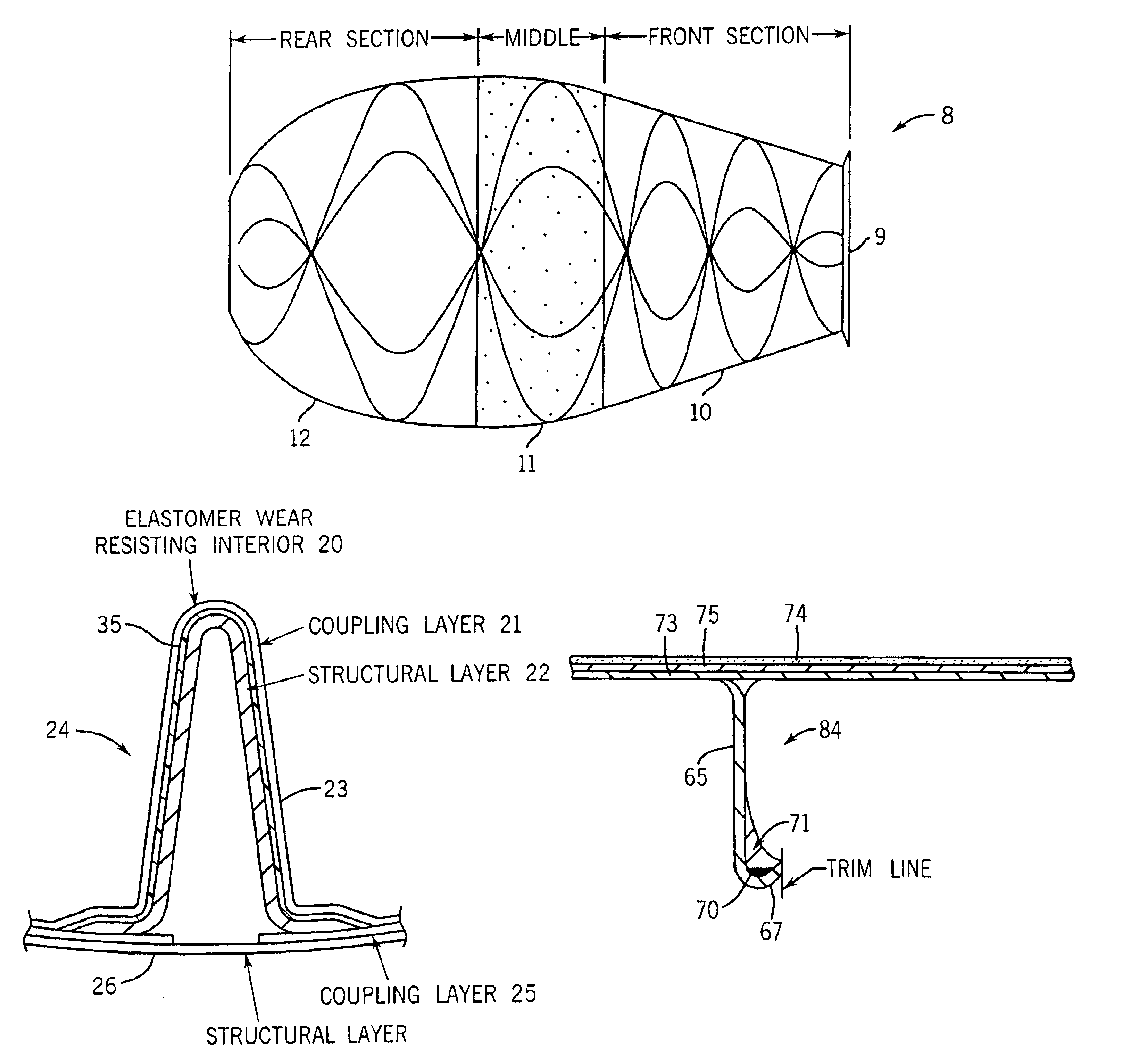
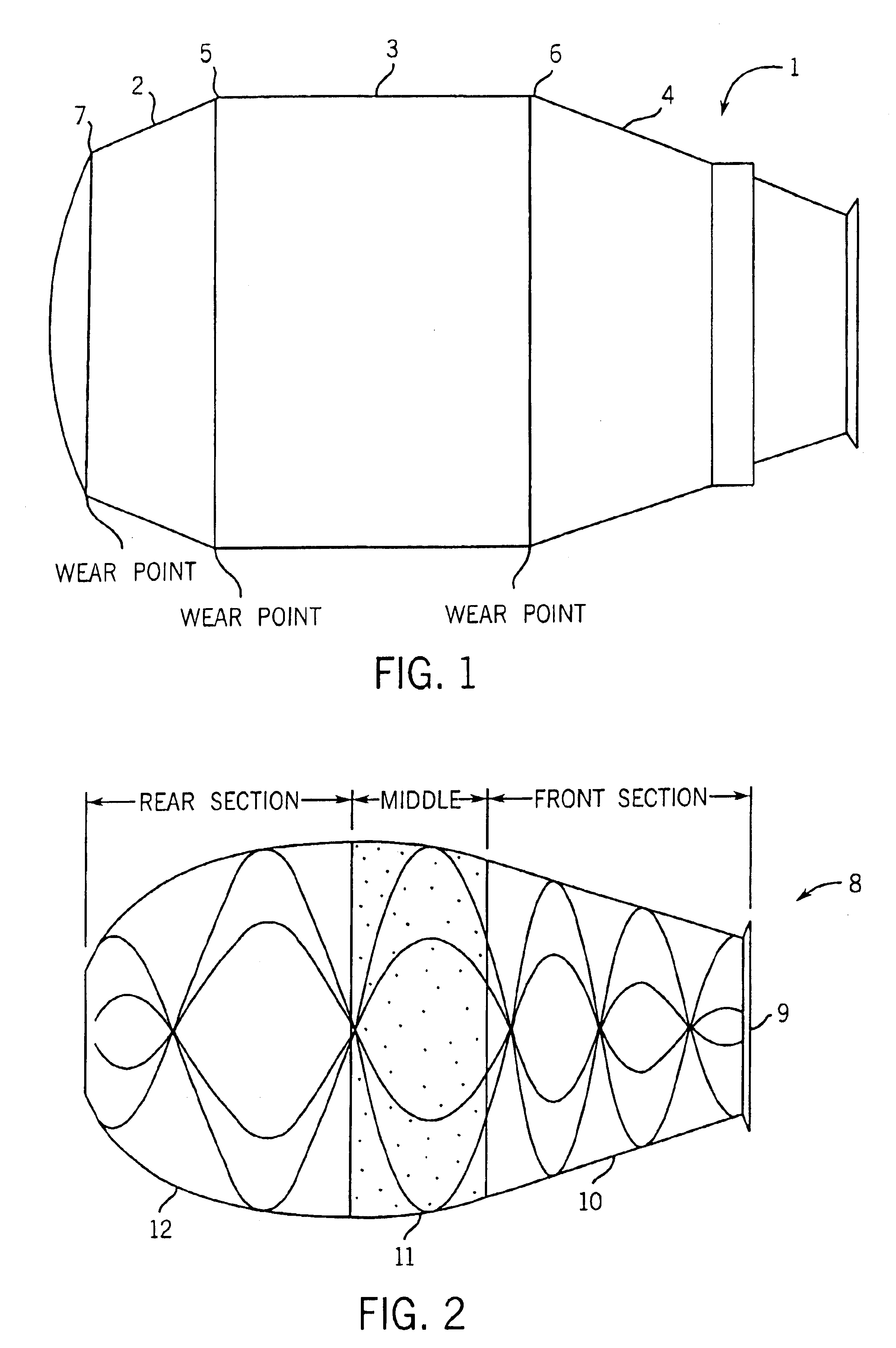
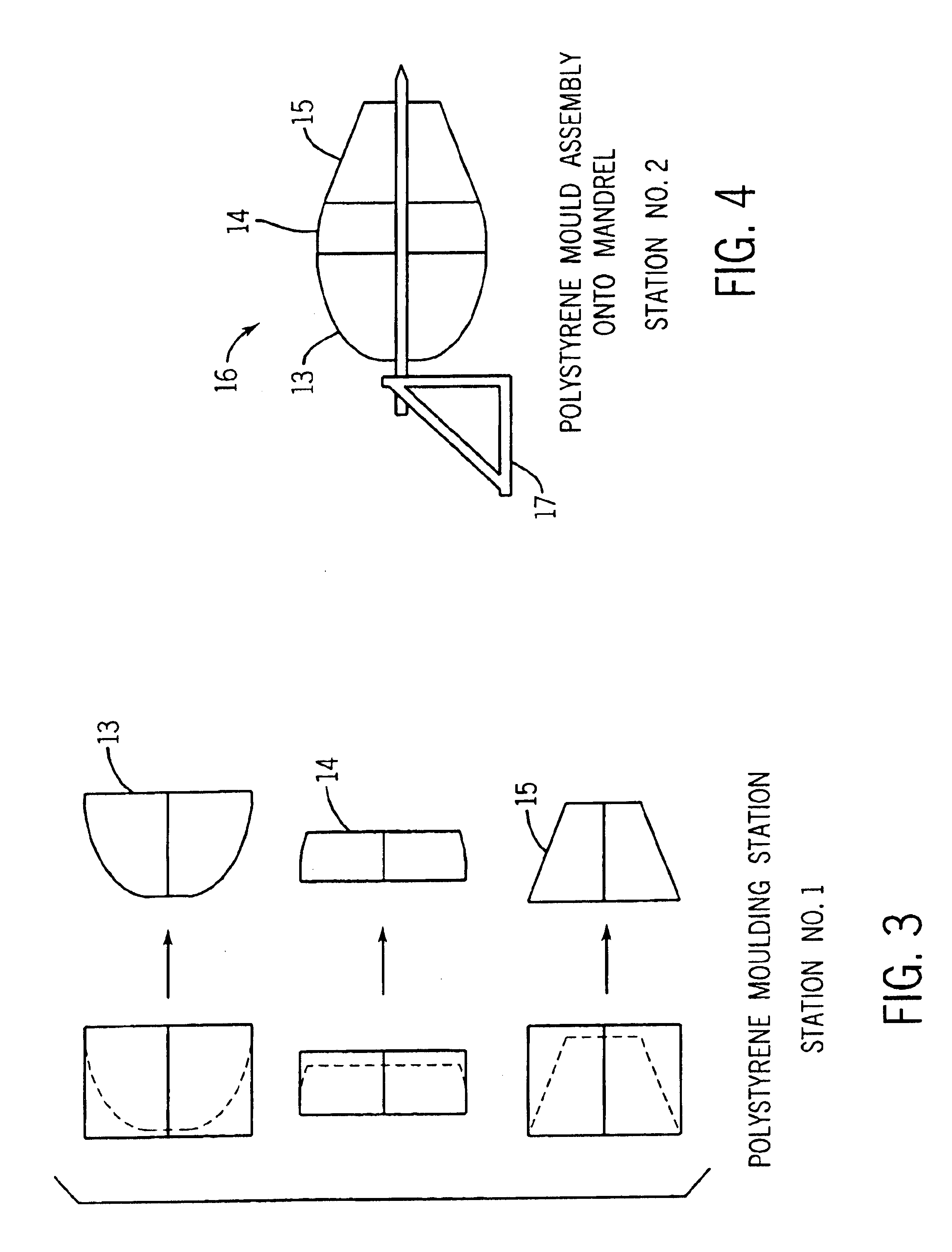
[0076]FIG. 1 shows an elevation view of a known steel mixing drum 1 which is typically constructed from separate prefabricated sections 2, 3 and 4 which are welded together at seams 5, 6 and 7. At seams 5, 6 and 7 the welded joints which are subject to concentrated wear due to the change in surface direction at the joint. The concentrated wear points in the prior art steel drums reduces the working life of the drums necessitating costly repair or replacement. Steel drums are fabricated from rolled flat sheets which form cones and a cylinder which are then joined together by welding. Archimedian spirals are then welded to the inner surface of the drum resulting in a high specific gravity vessel whose self weight reduces the amount of concrete which can be carried by the vehicle to which it is attached. As previously indicated, the steel drums suffer from a number of disadvantages including susceptibility to abrasion at the junctions of the cylindrical and conical sections and the ten...


PUM

PropertyMeasurementUnit
thicknessaaaaaaaaaa
thicknessaaaaaaaaaa
radiusaaaaaaaaaa

Abstract

A heavy duty rotary concrete mixing drum capable of attachment to a vehicle. The drum comprises a first end which engages a vehicle powered drive assembly which rotates the drum for mixing of said concrete and a second end from which mixed concrete is discharged. The drum is manufactured from at least one layer of plastics material; wherein the drum includes a wall having integral internal formations which promote mixing and discharge of said concrete and an inner surface which promotes mixing of the concrete.

Description

BACKGROUND[0001]The present invention relates to concrete mixing apparatuses and more particularly relates to a vehicle mounted plastics drum for mixing concrete and a methods manufacture thereof.PRIOR ART[0002]The building industry makes widespread use of concrete mixing trucks for transportation of ready mixed concrete to sites for concrete pours. These trucks typically comprise a large mixing assembly including a mixer drum mounted to the vehicle and which is connected to a mixer drive for mixing concrete contents during transportation and for discharge of the contents on site. The drive system comprises a gear box which takes power from the vehicle motor and which applies a mixing torque to the drum imparting axial rotation to the drum with the torque being adjustable depending upon the operating requirements. The above general arrangement is described in U.S. Pat. No. 4,585,356 which discloses a concrete mixer truck having a mixer drum adapted to be rotated by the traction moto...

Claims


Application Information

Patent Timeline
Patent Type & Authority Patents(United States)
IPC IPC(8): B29C33/40B29C41/22B29C70/04B29C70/30B29C70/08B29C70/32B28C5/42B28C5/00B29C33/52B29C33/60B29C33/56B01F29/60B28CB29C41/32B28C5/22B29CB29C70/06B29KB29K75/00B29K105/06B29LB29L24/00
CPCB28C5/4268B29C33/40B29C70/32B29C41/22B29C70/088B29C70/30B29C33/52B29C33/60B28C5/42B28C5/48
Inventor KHOURI, ANTHONYRODGERS, WILLIAM
Owner KHOURI ANTHONY
Learn More