Eureka AIR delivers breakthrough ideas for toughest innovation challenges, trusted by R&D personnel around the world.

Bodywork part with integrated antenna

Inactive Publication Date: 2005-05-31
MONTAPLAST +2
View PDF15 Cites 27 Cited by
  • Summary
  • Abstract
  • Description
  • Claims
  • Application Information

AI Technical Summary

Benefits of technology

[0004]The invention is therefore based on the object of providing a bodywork part which permits an antenna to be integrated and replaced in a particularly easy way.
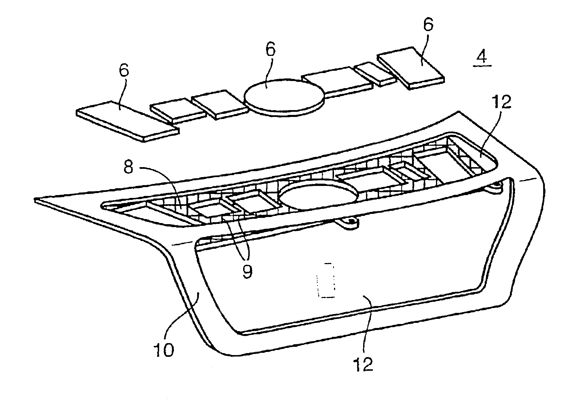
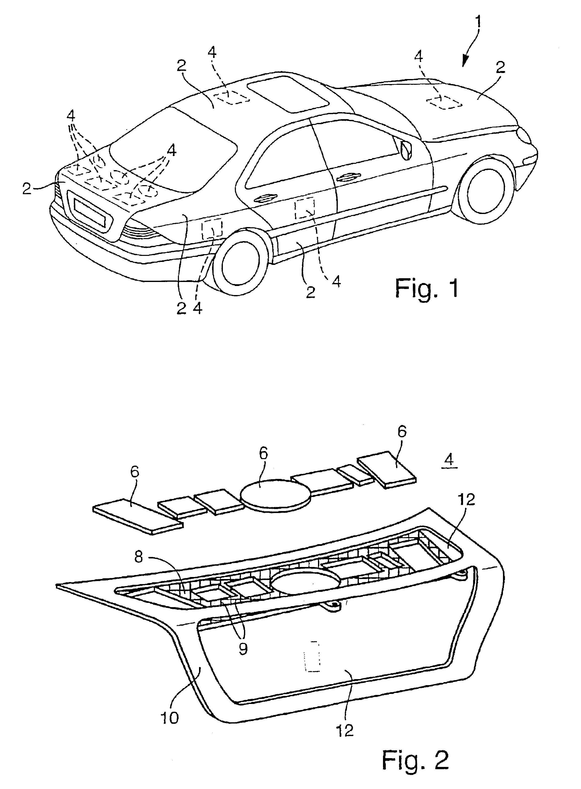
[0005]The object is achieved according to the invention by means of a bodywork part with an antenna arrangement integrated therein and with a carrier unit on which the antenna arrangement is detachably arranged. The advantages achieved with the invention lie, in particular, in the fact that the antenna arrangement can be inserted, together with the carrier unit, through cavities formed in the bodywork part, without further expenditure, in particular without additional shelf removal operations or cutting-out operations. In particular, the loss of rigidity of the bodywork caused by cutting-out operations is largely avoided by using the carrier unit and by its arrangement in cavities of the bodywork. In addition, such an antenna arrangement which is integrated into the bodywork part in a concealed fashion is not visible to the outside. This largely avoids the antenna arrangement being damaged by external influences. The detachable arrangement of the antenna on the carrier unit makes refitting and retrofitting, as well as complete replacement of individual antennas or of a plurality of antennas for different applications, possible in a particularly easy way. The cabling expenditure is kept particularly low. The antenna arrangement is prefabricated as a module and arranged on the carrier unit so that complex mounting operations are dispensed with. Furthermore, the antenna arrangement is integrated at a height which is sufficient for good reception, for example in the roof or in the tailgate of a vehicle. Furthermore, the cavities of the bodywork parts of the vehicle provide a particularly large installation space for the antenna arrangement.
[0008]For the most satisfactory degree of rigidity possible, the carrier unit has reinforcing ribs. The carrier unit is provided, for example, with transverse ribbing which ensures particularly high rigidity. A profile frame is preferably provided for receiving the carrier unit. Such a frame construction permits, in a supplementary fashion, a high degree of rigidity of the entire arrangement in the bodywork part with a simultaneously largely lightweight construction.
[0009]The carrier unit is expediently detachably arranged in a frame opening of the profile frame. The frame opening surrounds the carrier unit in a positively locking fashion. As a result, a particularly high degree of tensile strength and rigidity is provided, particularly in crash situations. Depending on the type and embodiment of the profile frame, one or more carrier units can be arranged horizontally and / or vertically therein. As a result, in addition to satellite-supported and / or terrestrial radio antennas, the use of navigation systems with related radar systems is made possible, in particular with a vertical arrangement.
[0010]The profile frame is advantageously formed from a metal. The profile frame is formed from a lightweight metal, for example aluminum. As a result, the profile frame serves as an earth reference connection for the antenna arrangement. Furthermore, owing to its frame design, the profile frame contributes largely to the rigidity of the bodywork.

Problems solved by technology

Furthermore, the cavities of the bodywork parts of the vehicle provide a particularly large installation space for the antenna arrangement.

Method used


Image

  • Bodywork part with integrated antenna
  • Bodywork part with integrated antenna
  • Bodywork part with integrated antenna

Examples


Embodiment Construction

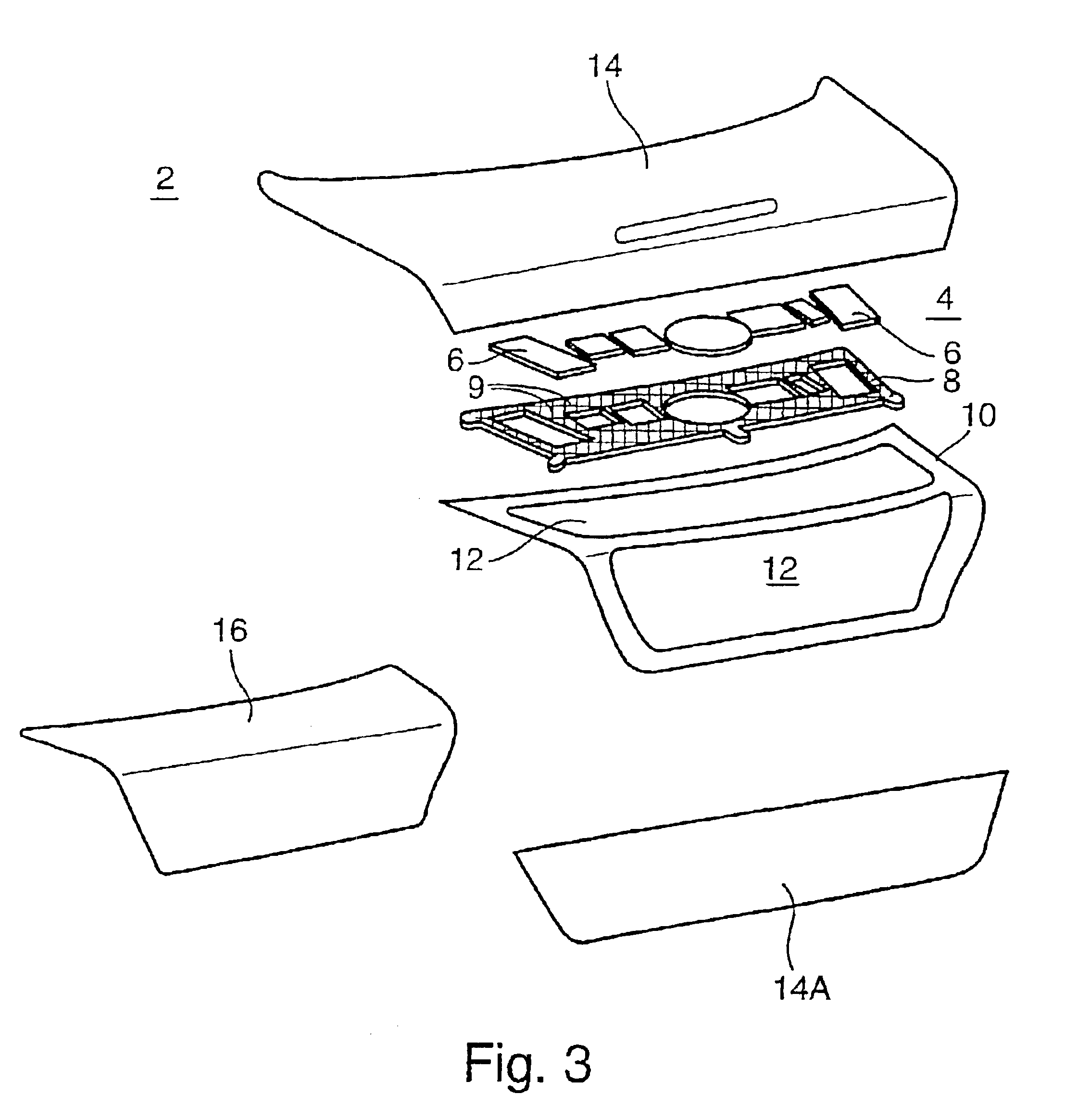
[0018]FIG. 1 illustrates a vehicle 1. The vehicle 1 has various bodywork parts 2 which are suitable for integrating an antenna arrangement 4. A part of a door, of a trunk lid, of a roof, of a fender, and / or of a hood, for example, serves as the bodywork part 2. The bodywork part 2 is permeable to electromagnetic waves. The bodywork part 2 is preferably formed from plastic, in particular from glass-fiber-reinforced thermoplastic, which is distinguished by particularly good rigidity, low anisotropy and particularly low longitudinal expansion at high temperatures and has little influence on the crash behavior as a result of thermal aging.

[0019]In particular, the outer paneling or outer shell of the bodywork part 2 is formed from a film in order to achieve the permeability to electromagnetic waves, and from a fiber-reinforced plastic material which is connected to this film by means of in-mold coating in an injection molding, compression molding or stamping process.

[0020]Possible films ...


PUM


Abstract

A bodywork part (2) is provided with an integrated antenna arrangement (4) and with a carrier unit (8) on which the antenna arrangement (4) is detachably arranged. This construction permits an antenna to be integrated and replaced easily.

Description

CROSS-REFERENCE TO RELATED APPLICATIONS[0001]This application is a continuation of International Application No. PCT / EP01 / 13994, filed Nov. 30, 2001, which was published in the English language on Jun. 13, 2002, under International Publication No. WO 02 / 47198 A2 and the disclosure of which is incorporated herein by reference.BACKGROUND OF THE INVENTION[0002]The invention relates to a bodywork part, in particular a vehicle bodywork part, with an antenna integrated therein.[0003]A vehicle has various antennas for various communications devices, for example radio, mobile radio or navigation systems. Radio antennas are embodied, for example, as window pane antennas. Such a window pane antenna is described, for example, in German Patent DE 44 15 675 C1. A rod antenna is usually used as a mobile radio antenna. Furthermore, German published patent application DE 42 15 659 A1 describes an antenna which is integrated into the bumper of the vehicle. As the number of communications services av...

Claims


Application Information

Patent Timeline
IPC IPC(8): H01Q1/32
CPCH01Q1/3291H01Q1/3275B62D25/105B62D29/005
Inventor SCHLIEBER, FRANKVOGT, RALFSCHMID, KLAUS-ERIKJAKOBI, REINHARD
Owner MONTAPLAST
Why Eureka
Eureka Blog
Learn More