Bottle carrier

a bottle carrier and bottle top technology, applied in the field of bottle carriers, can solve the problems of limited raising path, hand might readily touch the bottle top region where the crown cap is used, and limited cardboard material to be used, so as to facilitate carrying and enhance the stability of the bottle carrier

Inactive Publication Date: 2005-05-31
GRAPHIC PACKAGING INT EURO GERMANY
View PDF9 Cites 45 Cited by
  • Summary
  • Abstract
  • Description
  • Claims
  • Application Information

AI Technical Summary

Benefits of technology

[0014]The fact that the fork-shaped end portions extend into the adjoining side walls from the top wall causes the fork-shaped end portions to be slightly drawn in some areas into the bottle carrier when the strip-shaped central portion is raised. This enables the fork-shaped end portions to penetrate their fork prongs into the vacant spaces next to the necks of bottles, particularly in between the necks of adjoining bottles. This makes it possible to raise the strip-shaped central portion particularly distant from the bottles so that the gripping of the strip-shaped central portion bottles will be less disturbed by the bottles. What adds to this is that joining the ends of the fork-shaped end portions to the side walls allows to favourably introduce weighting forces into the handle portion and makes it possible to manage with a cardboard material which is less thick than that of conventional bottle carriers in which the handle strip has joined its ends to the top wall. This allows to employ a cardboard material having a smaller grammage or being of a less strong quality, and to save cost and weight.
[0040]According to an aspect, gripping holes are disposed in at least two opposed side walls. The gripping holes help the user in seizing the bottle carrier by two hands. This can be desirable, in particular, for container carriers having a large number of bottles (e.g. four times five bottles). According to a further aspect, the gripping holes are disposed in the side walls to which the fork-shaped end portions are joined at the end sides. Advantageously, the gripping holes are disposed in the narrow sides of the container carrier, which may facilitate carrying. According to a further aspect, the gripping holes are reinforced by the side flaps, e.g. by making the side flaps end at the upper borders of the gripping holes or by providing the side flaps with complementarily formed gripping holes. This prevents the bottle carrier, while being carried, from beginning to break in the area of the gripping holes. Furthermore, it is more agreeable to carry the bottle carrier by the gripping holes. For the same reasons, according to a further aspect, gripping tabs are disposed in the gripping holes that can be folded out for carrying or can be folded in.

Problems solved by technology

If such a bottle carrier is used there is a disadvantage that the hand might readily touch the bottle top regions where crown caps are.
Furthermore a strong cardboard material has to be employed to prevent the handle from rupture because of the considerable forces that act while it is being carried.
In addition, the raising path is limited by the fact that the handle strip will come to lie against the top areas of the articles in the vicinity of the end walls.
This involves relatively great technical expenditure in manufacture and leads to local material accumulations which can be a disturbance in storing the pre-glued cut-to-size pieces.
However, the handle portion is not reinforced here.
The raising path is limited by the fact that the handle strips will come to lie against the top areas of the end-side articles.

Method used


Image

  • Bottle carrier
  • Bottle carrier
  • Bottle carrier

Examples


Embodiment Construction

[0049]While this invention may be embodied in many different forms, there are described in detail herein a specific preferred embodiment of the invention. This description is an exemplification of the principles of the invention and is not intended to limit the invention to the particular embodiment illustrated.

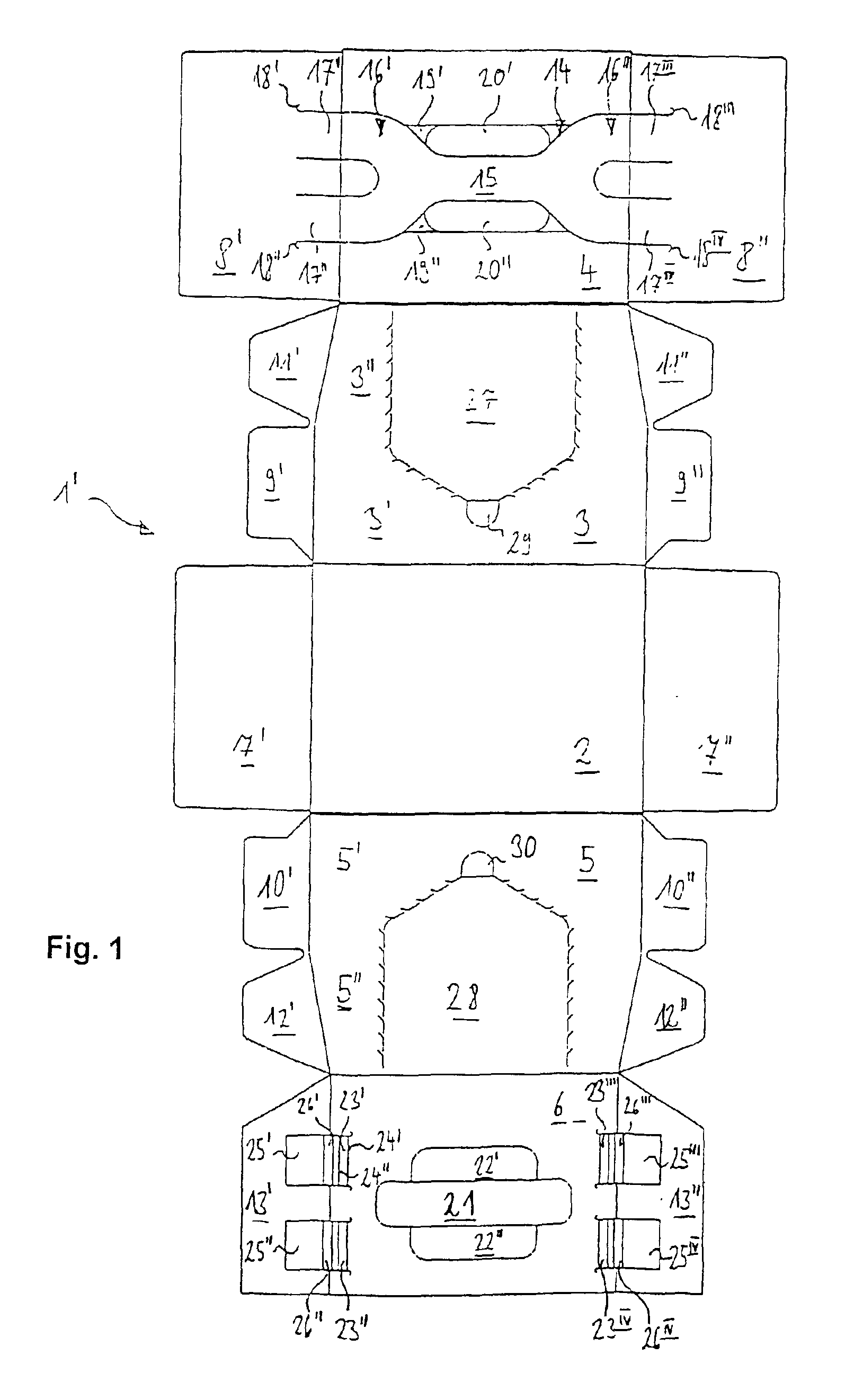
[0050]The cut-to-size piece 1′ of FIG. 1 has a bottom wall 2, a side wall 3 hinged to a longitudinal side of bottom wall 2, a side wall 5 hinged to another longitudinal side of bottom wall 2 and a top wall 6 hinged to another longitudinal side of side wall 5.

[0051]Side walls 3, 5 each have a lower side wall portion 3′, 5′ in the shape of a rectangle and an upper side wall portion 3″, 5″ in the shape of a trapezoid. Bottom wall 2, top wall 4, and further top wall 6 are rectangular with top wall 4 and further top wall 6 being of a slightly smaller longitudinal extension than is bottom wall 2.

[0052]The two transverse sides of bottom wall 2 have hinged thereto approximately recta...


PUM

PropertyMeasurementUnit
Electric potential / voltageaaaaaaaaaa
Areaaaaaaaaaaa

Abstract

A bottle carrier made of a foldable flat material, particularly cardboard, comprising a top wall, a bottom wall, side walls interconnecting the top wall and bottom wall at the sides, and a handle portion extending across the top wall and into two opposed side walls which is defined by weakening lines in the top wall and the side walls, has a strip-shaped central portion in the top wall and two fork-shaped end portions each of which extends into an adjoining side wall from the top wall and is joined to the side wall at the outer ends.

Description

CROSS-REFERENCE TO RELATED APPLICATIONS[0001]Not applicable.STATEMENT REGARDING FEDERALLY SPONSORED RESEARCH[0002]Not applicable.BACKGROUND OF INVENTION[0003]The invention relates to a bottle carrier made of a foldable flat material, particularly cardboard.[0004]Bottle carriers made of cardboard in the shape of a box enclosing a set of bottles on all sides have been known already. It is further known, that such bottle carriers, in a top wall, have two adjoining punched-out portions into which a hand may be inserted to carry the bottle carrier by a strip-shaped handle defined between the punched-out portions. If such a bottle carrier is used there is a disadvantage that the hand might readily touch the bottle top regions where crown caps are. Furthermore a strong cardboard material has to be employed to prevent the handle from rupture because of the considerable forces that act while it is being carried.[0005]U.S. Pat. No. 6,065,590 discloses an article carrier the top wall of which ...

Claims


Application Information

Patent Timeline
IPC IPC(8): B65D71/00B65D71/36
CPCB65D71/36B65D2571/00141B65D2571/00469B65D2571/00728B65D2571/00543B65D2571/00574B65D2571/0066B65D2571/00524
Inventor SKOLIK, BERNARDECKERMANN, JENSSCHEELCKE, HILGER
Owner GRAPHIC PACKAGING INT EURO GERMANY
Why Eureka
Try Eureka