Ball roller

Inactive Publication Date: 2005-05-24
TERAMACHI HIROSHI
View PDF29 Cites 1 Cited by
  • Summary
  • Abstract
  • Description
  • Claims
  • Application Information

AI Technical Summary

Benefits of technology

[0004]The present invention provides a ball roller that is three to four times as endurable as the ball while, unlike a conventional roller, it has no need to be supported in two directions, i.e., at the rolling surface and at the end surfaces. Moreover, owing to its unique shape, the ball roller causes low frictional resistance so that it can withstand large thrust load while it can be manufactured at low cost.

Problems solved by technology

Moreover, owing to its unique shape, the ball roller causes low frictional resistance so that it can withstand large thrust load while it can be manufactured at low cost.

Method used


Image

  • Ball roller
  • Ball roller
  • Ball roller

Examples


Embodiment Construction

[0014]Preferred embodiments of the present invention will be described hereunder in detail with reference to the accompanying drawings.

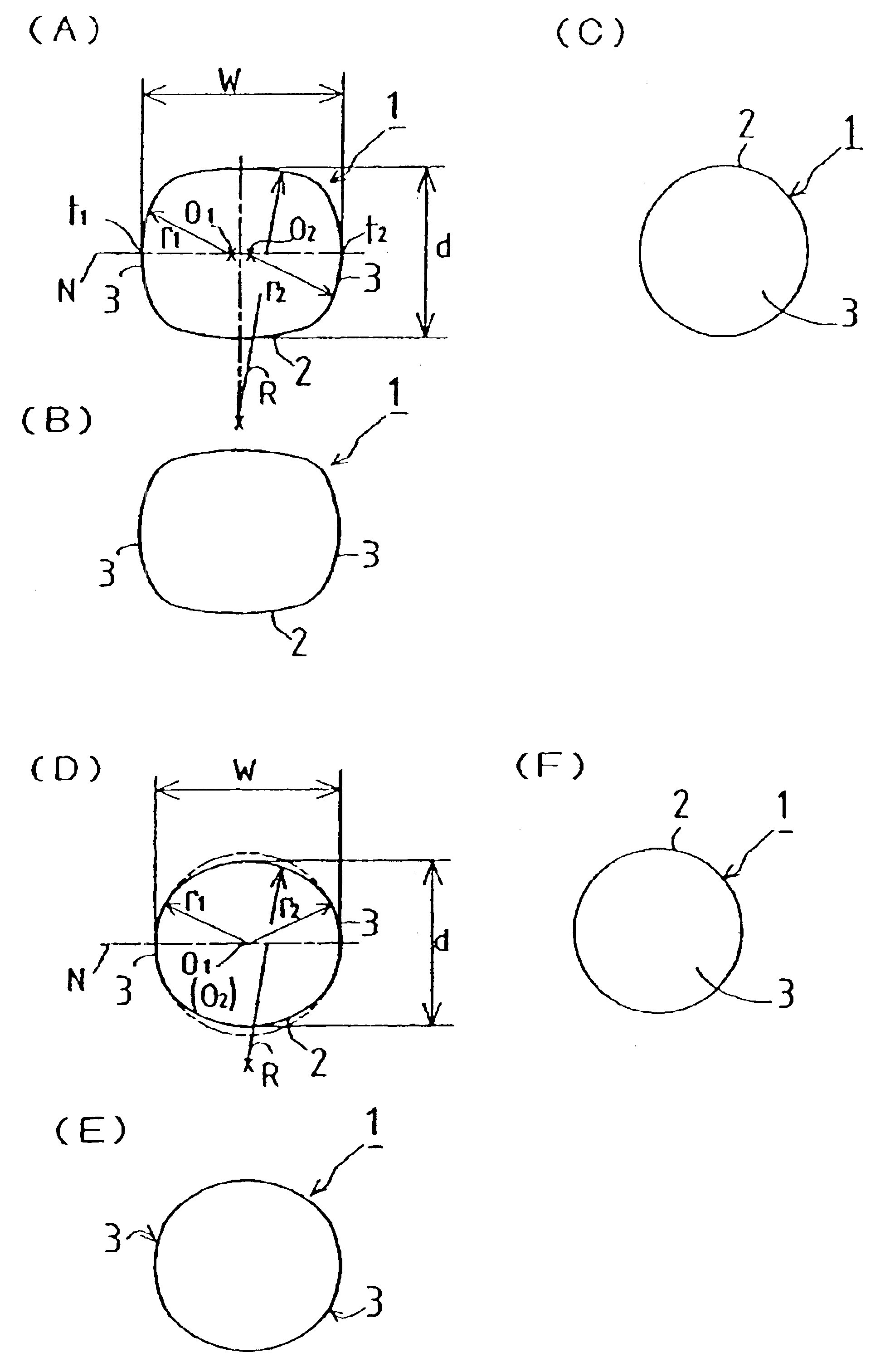
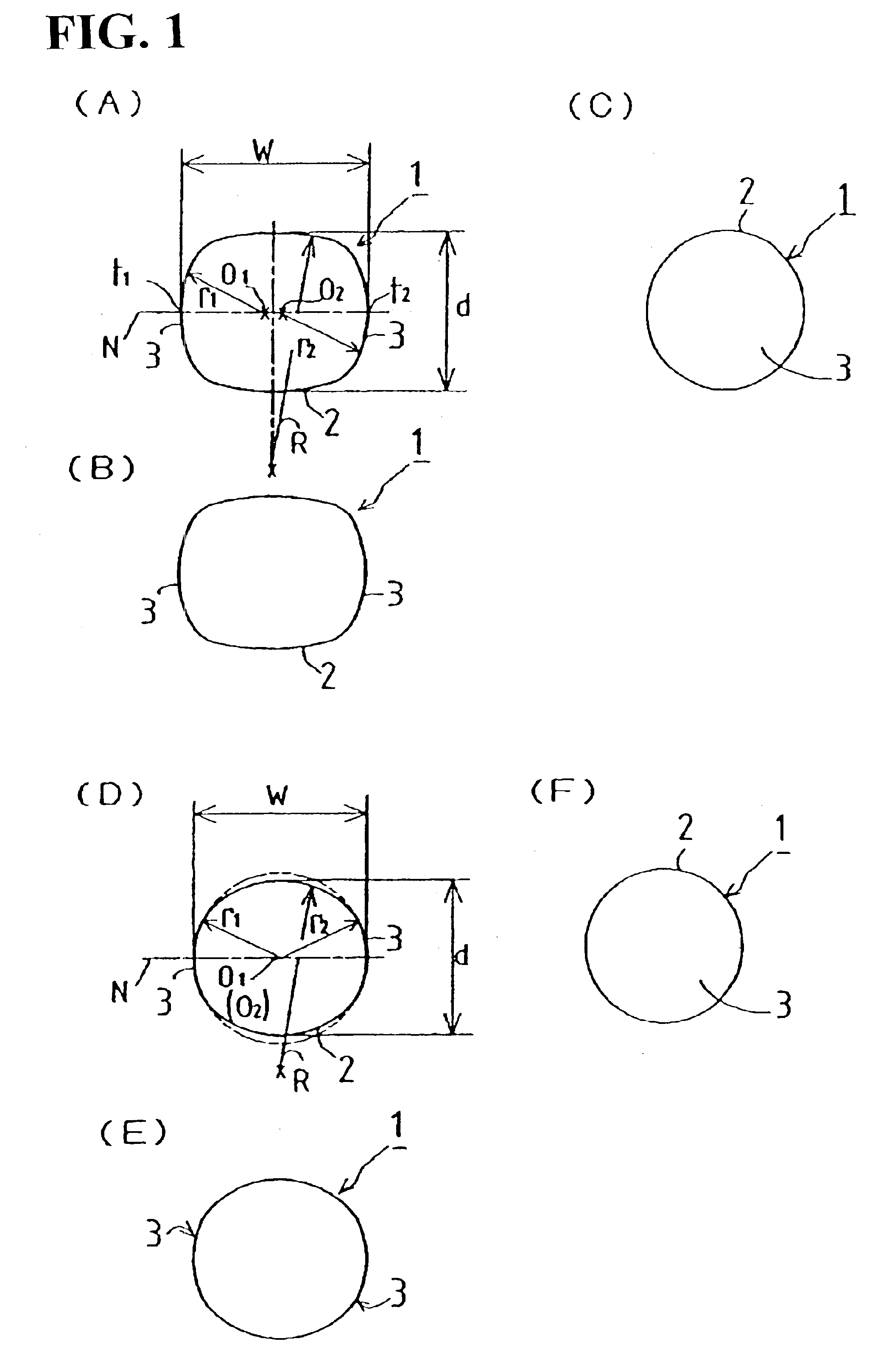
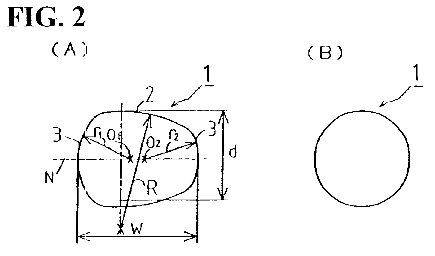
[0015]FIGS. 1(A) through 1(F) show ball rollers according to the present invention. The ball roller 1 has a rolling portion 2 having an arcuately protruding surface, and two spherical end portions 3, which protrude spherically from the right and left ends of the rolling portion 2. A curvature radius R of the rolling portion 2 is larger than curvature radii r1, r2 of the spherical end portions 3. Curvature centers O1, O2 of the spherical end portions 3 are both located on the rotational axis N of the rolling portion 2.

[0016]The maximum diameter of the rolling portion 2, which will be referred to as a short diameter d, is smaller than the distance between the two apexes t1 and t2 of the spherical end portions 3, which will be referred to as a long diameter W. A ratio between the short diameter d and the long diameter W falls within a range of approxima...


PUM


Abstract

The ball roller according to the present invention has a unique shape so that it can be handled just as easily as a conventional ball while being endurable against high load as is a roller. The ball roller comprises a rolling portion having an arcuate surface, and two spherical end portions spherically protruding from both ends of the rolling portion. The rolling portion has a radius of curvature larger than that of each of the spherical end portions, curvature centers of the spherical end portions are located on the rotational axis of the rolling portion. In another embodiment of the present invention, a ratio between the maximum diameter d of the rolling portion and the distance W between the two apexes of the spherical end portions falls within a rage of approximately 80%±17%.

Description

RELATED APPLICATIONS[0001]This application is a continuation-in-part of U.S. patent application Ser. No. 09 / 490,604 filed Jan. 25, 2000, now U.S. Pat. No. 6,398,417, which is hereby incorporated by reference.BACKGROUND OF THE INVENTION[0002]The present invention relates to a ball roller to be disposed for rotation between relatively movable parts that constitute a rolling bearing, a linear motion guide apparatus, a uniform motion joint or the like.[0003]Such a rolling member of conventional type for use in rolling bearings may be a ball or a roller. The ball, being in point contact, may have a small load capacity but has self-aligning ability and is easy to use. The ball is endurable against thrust load equal to about one-tenth of radial load. On the other hand, the roller, being in line contact, is about six times as endurable as the ball. But as shown in FIG. 4(C), each track 110 has to have a flange 111 for supporting an end surface 103 of the roller 100. In other words, the roll...

Claims


Application Information

Patent Timeline
IPC IPC(8): F16C33/36F16C33/30F16C33/34
CPCF16C33/36F16C2240/40F16C19/36
Inventor TERAMACHI, HIROSHI
Owner TERAMACHI HIROSHI
Why Eureka
Try Eureka