
Self-operated protection device for pipeline

a protection device and self-operated technology, applied in the direction of valve operating means/releasing devices, functional valve types, transportation and packaging, etc., to prevent leakage of fluid, reduce maintenance costs, and facilitate installation on the pipeline

Inactive Publication Date: 2005-05-24
ZENG XIANGWEI
View PDF7 Cites 3 Cited by
  • Summary
  • Abstract
  • Description
  • Claims
  • Application Information

AI Technical Summary

Benefits of technology

[0018]The protection device with the above-mentioned structure has the following advantages and effects.
[0019]1. The flow-sensing device and the control cylinder of the present invention utilizes the dynamic pressure difference at the two ends of the flow-sensing tube of the flow state-sensing device. The pressure difference is generated by the abrupt change of the flow rate of the fluid in the fluid pipe caused by the fluid leakage due to the rupture of the pipeline and pushes the valve core, so that the valve core and the valve seat, which are normally in a closed state, change to an open state. The fluid enters the control cylinder from the flow-sensing tube via the valve seat and the flow state-control tube, pushing the control piston which closes the main valve by means of the transmission of the control rod and the main valve stem. As a result, the pipeline is protected and leakage loss of the fluid is prevented. After the main valve is closed, the valve core is restored under the action of the restoring spring, and the valve core and the valve seat are in a closed state. When the trouble is removed, it is possible to make the main valve return to its open position again by operating the control cylinder, thereby achieving the control of the main valve. The present invention has the advantage of self-operatedly controlling the closing and opening of the main valve to protect a fluid pipeline by using fluid kinetic energy. Particularly, since the flow state-sensing device can receive the change of the fluid kinetic energy on both sides of the main valve, the invention has the advantage of being able to carry out bidirectional sensing. There is no need for manual operation.
[0020]2. The present invention has an integral structure with the flow state-sensing device being provided in the flow passage of the main valve core of the main valve, thus having a small overall volume and being convenient to be installed on a pipeline. The gas pocket in the pressure accumulating cylinder accumulates pressure energy in the early part of the period, during which the fluid enters the control cylinder via the pressure accumulating cylinder, when the kinetic energy of the fluid is larger. The pressure energy is released in the later part of the period when the kinetic energy of the fluid is smaller with the main valve being gradually closed, thereby ensuring the reliable closing of the main valve.
[0021]3. With a solenoid valve being provided at the cylinder port of the control cylinder in the self-operated protection device of the invention, the remote control of the protection device can be achieved. With a manually operated valve being provided at the cylinder port of the control valve, after self-operatedly closing the main valve through the flow state-sensing device and the control valve, the valve is opened manually to have the main valve and the control cylinder restored.
[0023]5. According to the invention, the control rod of the control cylinder and the main valve stem forms a rack and gear mechanism, thus having a simple structure and being reliable in operation.

Problems solved by technology

Such a pipeline protection system has a complicated structure and a long signal transmission route, and it is therefore necessary to utilize external forces generated by energy cumulating tanks and the like to achieve the protection of pipelines.

Method used


Image

  • Self-operated protection device for pipeline
  • Self-operated protection device for pipeline

Examples


embodiment 1

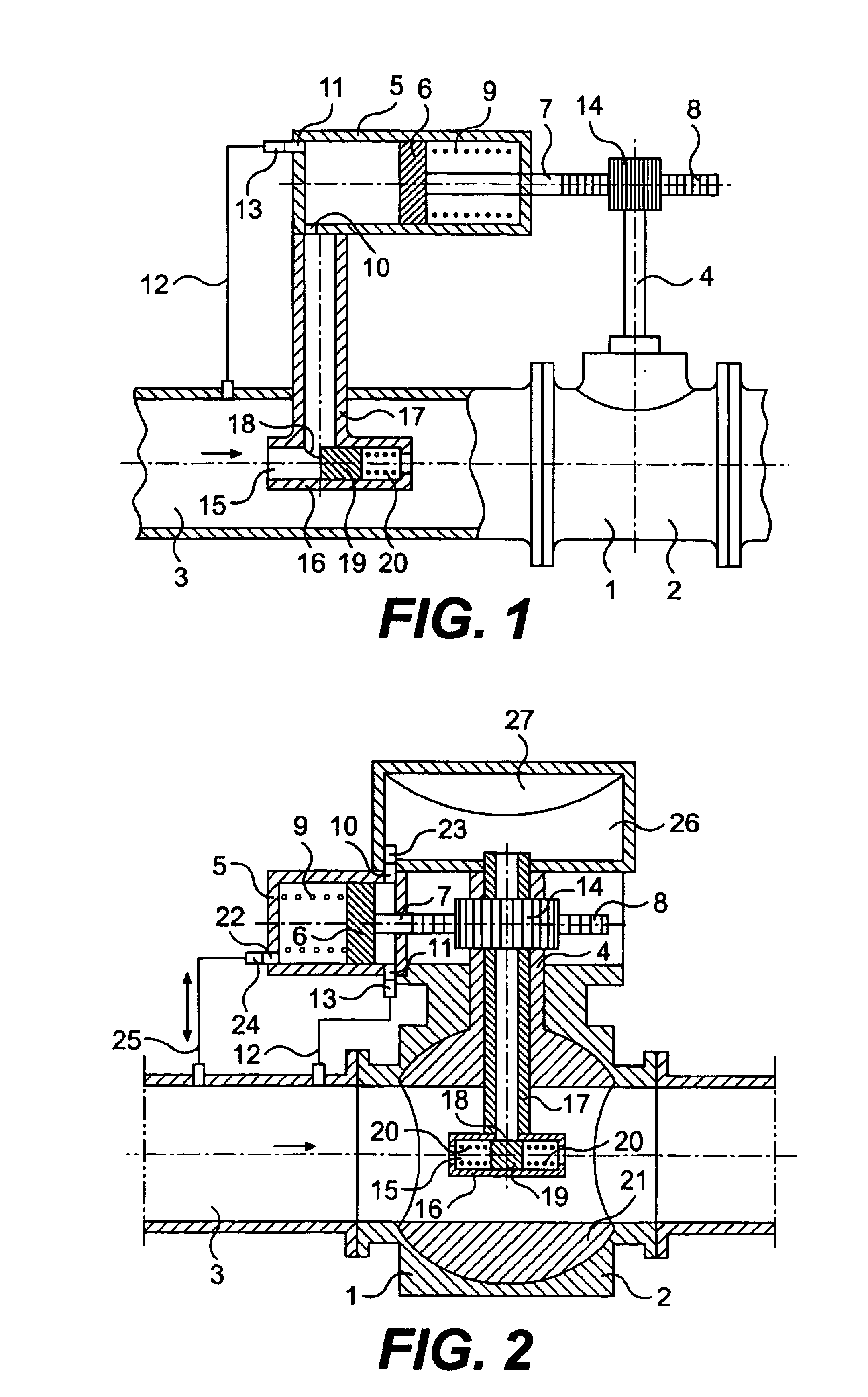
[0027]As shown in FIG. 1, the self-operated protection device for pipeline of the first embodiment of the present invention is comprised of a main valve 1 and a control device. The control device is comprised of a control cylinder 5, a fluid state-sensing device 15 and etc.

[0028]The main valve 1 comprises a valve body 2 having a cavity of a conventional shape and is connected to a fluid pipe 3 in a conventional manner. On the upper end of the valve body there may be provided a valve cover. The valve body can be integral with the valve cover as usual, or they can be separate members and coupled with each other through a flange. The main valve stem 4 of the main valve can be fixedly connected to the main valve core of the main valve, and the main valve with such a structure can be a ball valve, a control valve, a stop valve and etc. The main valve stem 4 can also be rotatably connected to the valve core of the main valve, the valve core being able to reciprocate. The main valve with s...

embodiment 2

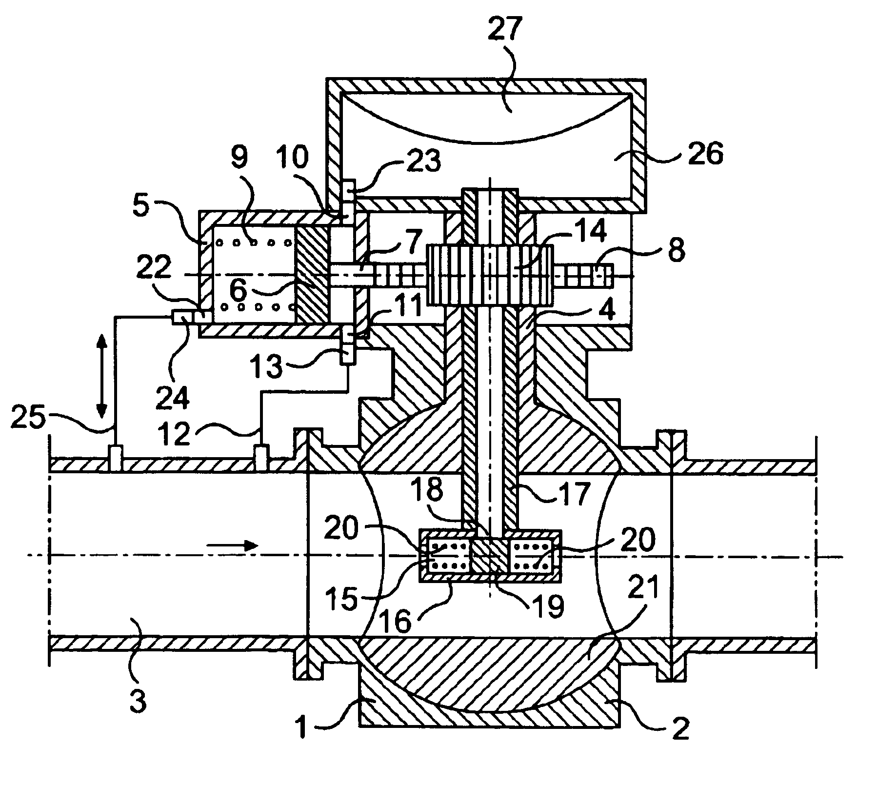
[0035]As shown in FIG. 2, the self-operated protection device for pipeline of the second embodiment of the invention is comprised of a main valve and a control device, the control device being comprised of a control cylinder 5, a flow state-sensing device and etc.

[0036]The structure of the main valve 1 of the second embodiment is substantially the same as that of the first embodiment. A ball valve is used as the main valve, the main valve stem 4 is formed into a circular tube, and the tube is communicated with the flow passage of the main valve core 21.

[0037]The structure of the control cylinder 5 of the second embodiment 2 is substantially the same as that of the first embodiment 1. The control cylinder is transversely arranged and is connected to the valve cover on the upper end of the main valve on the left side of the valve cover. At the right end of the control cylinder there are a cylinder port 10 and a cylinder port 11, and at the left end there is a cylinder port 22. At the ...


PUM


Abstract

A protection device which is capable of cutting off a pipeline when the pipeline leaks due to the rupture of the pipe self-operatedly closes the pipeline using fluid kinetic energy. A control rod converts linear movement of a piston into the opening and closing movement of a main valve core. The piston separates a hydraulic cylinder chamber into a first chamber and a second chamber. A restoring spring in the first chamber restores a control piston to an initial position. A control valve in the second chamber controls discharge of fluid from the second chamber. A flow state-sensing device introduces fluid in the fluid pipe to the second chamber when the fluid pipe ruptures and leaks.

Description

[0001]The present application is a continuation of U.S. application Ser. No. 10 / 240,008, filed Mar. 4, 2003, now abandoned, the entire disclosure of which in incorporated by reference herein which is the National Stage of International Application No. PCT / CN01 / 00139, filed Feb. 22, 2001.FIELD OF THE INVENTION[0002]The present invention relates to a control device for fluid pipelines, and particularly to a protection device which is capable of automatically cutting off the pipelines for long distance fluid-transportation when leakage occurs due to pipe rupture.BACKGROUND OF THE INVENTION[0003]Conventional protection devices for pipelines are provided with a coupled gas-liquid emergency cut-off system. When a signal is generated indicative of a pressure drop caused by a pipe rupture, the system utilizes a plurality of valves and energy accumulating tanks to multistagedly transmit, transform and amplify the signal to generate a thrust large enough to push a hydraulic driving device so ...

Claims


Application Information

Patent Timeline
Patent Type & Authority Patents(United States)
IPC IPC(8): F16K17/32F16K31/54F16K31/16F16K31/163F16K31/44F16K17/20F16L55/10F16K17/34F16K17/36F16L57/02F17D5/02
CPCF16K17/32F16L55/1015F16K31/54F16K31/1635Y10T137/7727Y10T137/7768Y10T137/7759
Inventor ZENG, XIANGWEI
Owner ZENG XIANGWEI
Learn More