Method of producing optical fiber preform
a technology of optical fiber and preform, which is applied in the direction of glass deposition burners, manufacturing tools, instruments, etc., can solve the problems of not adjusting the j ratio method, increasing the limit of rotating speed, and further generating new problems, so as to reduce the generation of voids by mixing impurities into soot, and the cost of equipment is low
- Summary
- Abstract
- Description
- Claims
- Application Information
AI Technical Summary
Benefits of technology
Problems solved by technology
Method used
Image
Examples
example 2
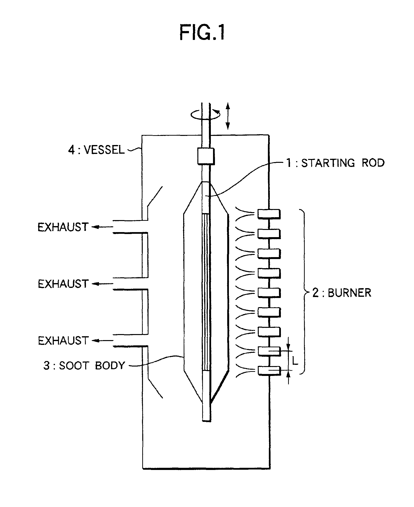
[0057]Except that the burner interval is 200 mm, under the same apparatus structure, starting rod, target J ratio, and traverse condition as Example 1, the soot deposition is conducted at the rod reciprocating speed of 703 mm / minute and the axis rotating speed of 30 and 50 rpm. Then the gas is taken away from soot and the vitrification is conducted to obtain the transparent optical fiber preform. As the result, the gap of the average J ratio in the longitudinal direction from the target J ratio is 0.2 times at 30 rpm (J ratio rate 6.7%), and 0.1 times at 50 rpm (J ratio rate 3.3). Further, J ratio fluctuation in the longitudinal direction (the rate of the unevenness to the diameter of the soot body) is 3.5% at 30 rpm, and 2% at 50 rpm.
example 3
[0058]Except for that the burner interval is 200 mm, under the same apparatus structure, starting rod, target J ratio, and traverse condition as Example 1, the soot deposition is conducted at the rod reciprocating speed of 1503 mm / minute and the axis rotating speed of 90 rpm. After that, the deaeration and vitrification are conducted to obtain the transparent optical fiber preform. Because the reciprocating speed is high, and the soot deposition amount per the averaged number of turns is small, the J ratio adjustment becomes easy. The gap of the average J ratio in the longitudinal direction from the target J ratio in the optical fiber preform is 0.11 times (J ratio rate 3.7%). The J ratio fluctuation in the longitudinal direction is 3% by increasing the reciprocating speed.
example 4
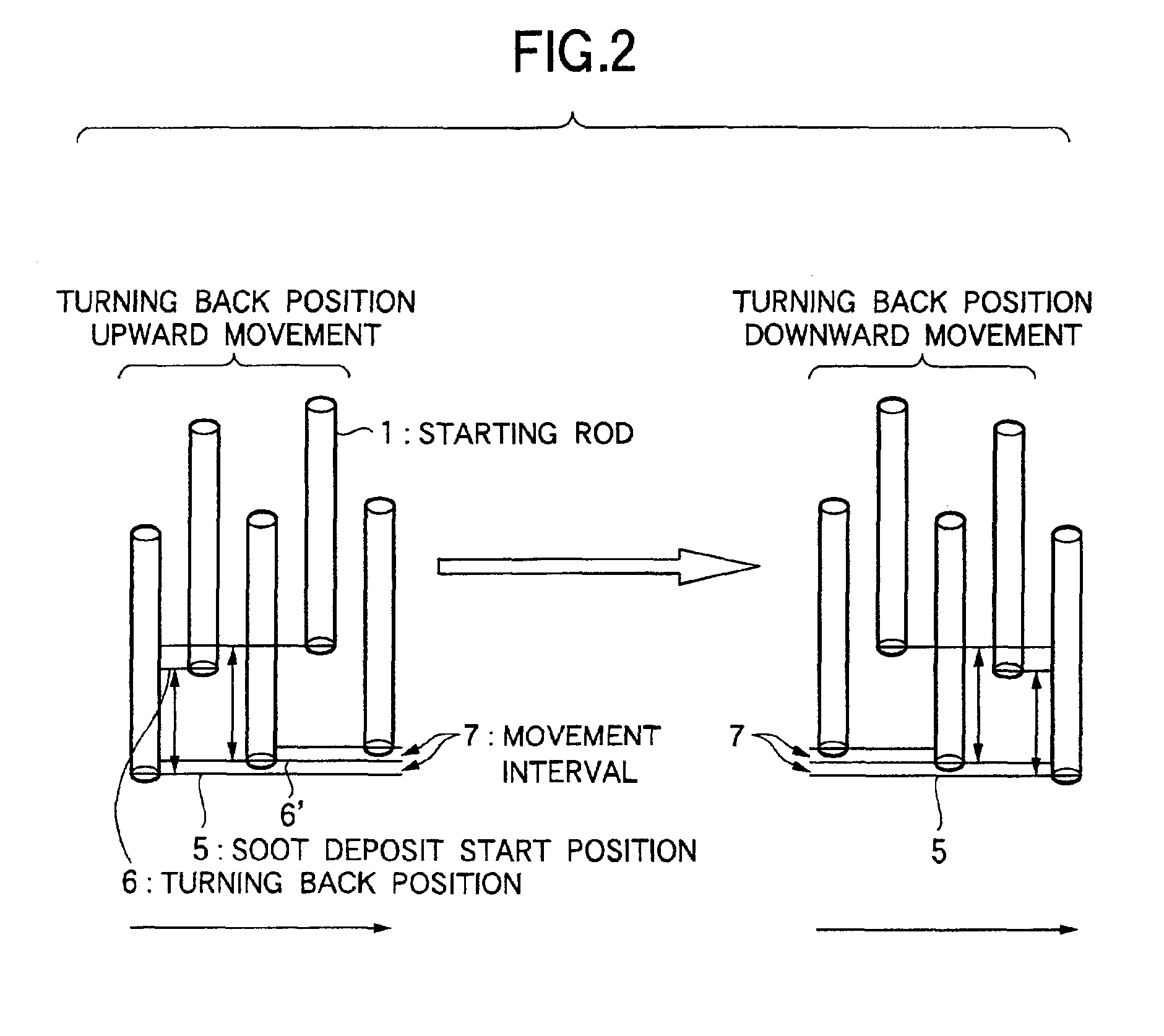
[0059]Except that the burner interval is 200 mm, under the same apparatus structure, starting rod, target J ratio, and traverse condition as Example 1, the soot deposition is conducted at the rod reciprocating speed of 800 mm / minute and the axis rotating speed of 40 rpm. After that, the deaeration and vitrification are conducted to obtain the transparent optical fiber preform. In this example, because the center line of the soot spirally deposited by one traverse, is almost overlapped with the center line of the soot deposited at the preceding traverse, thereby the J ratio fluctuation becomes large. The gap of the average J ratio in the longitudinal direction from the target J ratio is 0.17 times (J ratio rate 5.7%), and the J ratio fluctuation in the longitudinal direction is 3.7%.
PUM
| Property | Measurement | Unit |
|---|---|---|
| Length | aaaaa | aaaaa |
| Current | aaaaa | aaaaa |
| Current | aaaaa | aaaaa |
Abstract
Description
Claims
Application Information
 - R&D
- Intellectual Property
- Life Sciences
- Materials
- Tech Scout
- Unparalleled Data Quality
- Higher Quality Content
- 60% Fewer Hallucinations
Browse by: Latest US Patents, China's latest patents, Technical Efficacy Thesaurus, Application Domain, Technology Topic, Popular Technical Reports.
© 2025 PatSnap. All rights reserved.Legal|Privacy policy|Modern Slavery Act Transparency Statement|Sitemap|About US| Contact US: help@patsnap.com


