Apparatus for coating moving fiber webs

a technology of moving fiber and apparatus, which is applied in the direction of application, lighting and heating apparatus, and drying machines with progressive movements, etc. it can solve the problems of sharp bending of paper webs at the turning point, and affecting the quality of coating, so as to avoid the effect of quality impairing effects on the web during turning, saving valuable construction space, and improving the quality of coating webs

Inactive Publication Date: 2005-05-24
VOITH PATENT GMBH
View PDF14 Cites 0 Cited by
  • Summary
  • Abstract
  • Description
  • Claims
  • Application Information

AI Technical Summary

Benefits of technology

[0012]In the present invention the length of the web's free motion, i.e. the length of the path of the web between two guiding elements which are in contact with the web, is extended compared with the coating apparatuses known from prior art. This is even more extraordinary since many experts are of the opinion that, with an increase in the length of the free motion, the instability of the web's path also increases and that therefore the expert should be urged to reduce the length of free motions. Surprisingly, the advantageous effects of the present invention can be achieved without taking additional measures or installing further components for increasing the stability of the web's path when moving through the coating apparatus.
[0013]In addition to the fact that quality impairing effects on the web during turning are avoided, a further advantage can be achieved by the coating apparatus of the present invention: in contrast to the coating apparatus known from prior art, it is now possible to apply at a coating station a coating material onto both sides of the web because of the planar and externally unaffected path of the web after leaving the coating station. Thus, the space, especially the longitudinal dimension required by the coating apparatuses in which a web is to be double-coated once or several times, can be considerably reduced. This means that valuable construction space can be saved.
[0014]The coated web's quality can be further improved by having the web leave the coating station in an upward direction, preferably in an essentially vertical direction. It is often the case that when the web separates, for example, from the applicator roll or a similar coating element used for indirectly applying a coating material onto the web, an effect called “misting,” occurs, i.e., a vapour of small coating beads or droplets is formed in the wedge between the web and the surface of the coating element. If the web is, however, leaving the coating station in an upward direction, preferably in an essentially vertical direction, the probability that the small beads fall on the coated web decreases with the increasing pitch angle. The beads are rather more likely to fall back on the coating element instead.
[0015]It is, however, also conceivable that the web could leave the coating station in a downward direction. This can be especially helpful in cases where already existing coating apparatuses and / or devices with non-contact turning apparatuses are to be converted in such a way that the web is traveling in one plane only without changing direction between leasing the coating station and entering the non-contact turning apparatus.
[0016]As has already been mentioned, the free motion of the web after the coating station serves the purpose of extracting humidity from the web. If the web is leaving the coating station in an upward or downward direction, there is a sufficient path for the web to dry without having to increase the length of the coating apparatus and, with it, its need of space since, in this case, the turning apparatus can be located either essentially above or underneath the coating station.
[0017]The non-contact turning apparatus can turn the web by approximately 90°. This is advantageous if web processing units of great length, e.g. a calender, follow the turning apparatus. The web can, for example, leave the coating station in a vertically upward direction, be turned by the turning apparatus by 90° to a machine running direction and then be led back to the height level of the coating station by a vertically arranged calender. In doing so, the available construction space can be used optimally by arranging the web processing units in a compact way. The machine running direction is the direction the web travels, starting with unwinding the web supply to be coated to reeling in the coated web.

Problems solved by technology

One disadvantage of this prior art coating apparatus is, on the one hand, that the coating is negatively influenced by turning the humid paper web before it has at least partially dried.
This disadvantage tends to be even more pronounced since, due to the construction space available, turning rolls with small roll diameters are usually used which leads to a sharp bending of the paper web at the turning point.
In addition, the use of such a turning roll makes it impossible to convert a coating apparatus to an apparatus with which double-coating can be realized since, in this case, the turning roll would be in direct contact with the humid coating which would intolerably influence the coating's quality.

Method used


Image

  • Apparatus for coating moving fiber webs
  • Apparatus for coating moving fiber webs
  • Apparatus for coating moving fiber webs

Examples


Embodiment Construction

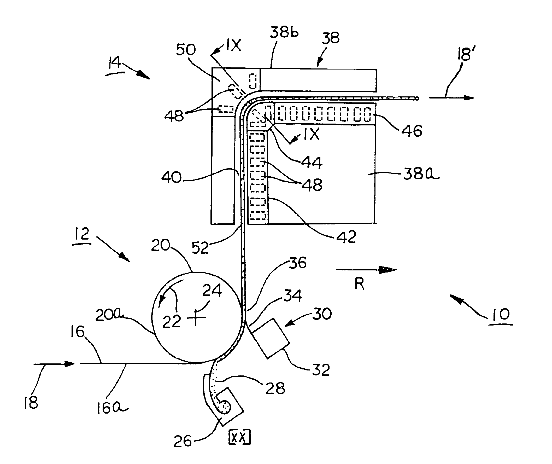
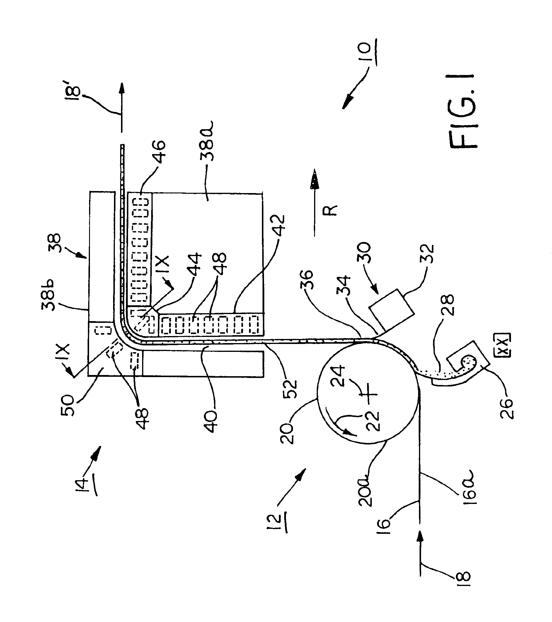
[0065]In FIG. 1 a coating apparatus 10 includes a coating station 12 as well as a non-contact turning apparatus 14. A web 16 moves into coating station 12 in the direction of arrow 18.

[0066]Coating station 12 includes a support element in form of a support roll 20 which rotates in the direction of arrow 22 around axis 24 thereof, axis 24 being perpendicular to the drawing plane of FIG. 1 in such a way that web 16 is supported slip-free by circumference 20a of support roll 20.

[0067]Coating station 12 further includes a coating unit 26 from which a liquid coating material 23 is directly applied onto side 16a of web 16 not facing support roll 20. In the moving direction 18 of web 16, after coating unit 26, an equalizing apparatus 30 is provided. Equalizing apparatus 30 includes a stiff beam 32 on which a doctor blade 34 is mounted for metering and equalizing liquid coating 28 applied onto web 16. In the moving direction 18 of web 16, web 16, now layered with coating 28, separates from ...


PUM

PropertyMeasurementUnit
diametersaaaaaaaaaa
temperatureaaaaaaaaaa
lengthaaaaaaaaaa

Abstract

An apparatus for coating a moving web, in particular a paper or cardboard web, on one or both sides with a liquid or pastous coating material includes a coating station for applying the coating material onto the web, as well as a non-contact turning apparatus following the coating station in the moving direction of the web. The web moves in only one plane from the point of exit from the coating station to the point of entry into the non-contact turning apparatus, without changing direction.

Description

[0001]This application is a DIV of 09 / 967,154 filed Sep. 28, 2001 now U.S. Pat. No. 6,634,120.BACKGROUND OF THE INVENTION[0002]1. Field of the Invention[0003]The present invention concerns an apparatus for coating one or both sides of a moving fiber web, in particular a paper web or a carton (i.e., cardboard) web, with a liquid or pastous coating material, the apparatus including a coating station for applying a coating onto the web and a non-contact turning apparatus following, viewed in the web's moving direction, the coating station.[0004]2. Description of the Related Art[0005]From WO 98 / 32921 an apparatus for coating a paper web on one side which includes a coating station and a non-contact turning station is known. After the coating station, in which a coating material is applied onto the moving paper web with the moving paper web being supported by a backing roll, the paper web moves on to a turning roll. From there it travels to a non-contact turning and driving apparatus and...

Claims


Application Information

Patent Timeline
Patent Type & Authority Patents(United States)
IPC IPC(8): D21F5/00D21F5/18D21H25/06D21H23/70D21H25/00D21H23/00D21H23/22F26B13/10F26B13/20B05C9/00B05C9/04B05C9/12B05C9/08
CPCD21F5/18F26B13/104D21H23/70D21H25/06D21H23/22B05C9/04B05C9/12
Inventor HELMER, KNUTBOWDEN, EDWIN V.
Owner VOITH PATENT GMBH
Why Eureka
Try Eureka