Branching unit and system for underwater optical communication

a technology of optical communication and branching unit, which is applied in the direction of line-transmission details, electromagnetic repeaters, instruments, etc., can solve the problems of prolonging the decay of magnetic field and thus the dropout time of relays, high current surges that may damage relays, etc., to prolong the decay of magnetic field and increase relay dropout time

Inactive Publication Date: 2005-05-17
ALCATEL LUCENT SAS
View PDF9 Cites 25 Cited by
  • Summary
  • Abstract
  • Description
  • Claims
  • Application Information

AI Technical Summary

Benefits of technology

[0007]FIG. 1 shows three rectifier bridges, one around each of the relay coils A, B, C. These rectifier bridges ensure that no matter which direction current flows (between the terminal) the coil energizing current is always unipolar, and they also help to increase relay dropout time via the flywheel effect. Under fault conditions, current flow through the branching unit may suddenly reverse as the cable discharges into a short circuit. This reversed process may be quite slow for distant faults, thus there is a time when an actuated relay is starved of current and, furthermore, it must remagnetise with the opposite polarity. In short, the relay may unswitch and connect the spur cable to the main trunk cable causing a high current surge that may damage the relay, depending on the voltage at the time. Additionally the coil bridges act as “flywheels”. Removal of current supply will cause a coil to generate a back voltage, the polarity of which is conducted by the bridge diodes. The diode conduction will further prolong the magnetic field decay and thus the dropout time of the relay. This damping effect is sufficient to hold a relay in during the line current reversal and so prevent a grounded spur being connected to the trunk line. Due to the inclusion of the bridge diodes around the relay coils A, B, C, linearity bypass resisters 130 are included across each of them, since at low supply voltages these bridge diodes will not conduct.
[0008]There are four power demand circuits in the form of regenerators 120 in the illustrated arrangement, although this is not the only possibility, with their power feed circuits connected in series. A respective zener diode 121 is connected across (in parallel with) each regenerator 120 and limits supply voltage to the regenerator, the four zener diodes 121 being connected in series. The arrangement of four zener diodes 121 is in effect disposed in parallel with each relay coil A, B and C.

Problems solved by technology

However, that circuit does not carry out any optical switching but is simply to provide power for respective in-line signal boosters (e.g. regenerators or amplifiers) for the various cables.
This reversed process may be quite slow for distant faults, thus there is a time when an actuated relay is starved of current and, furthermore, it must remagnetise with the opposite polarity.
In short, the relay may unswitch and connect the spur cable to the main trunk cable causing a high current surge that may damage the relay, depending on the voltage at the time.
The diode conduction will further prolong the magnetic field decay and thus the dropout time of the relay.

Method used


Image

  • Branching unit and system for underwater optical communication
  • Branching unit and system for underwater optical communication
  • Branching unit and system for underwater optical communication

Examples


Embodiment Construction

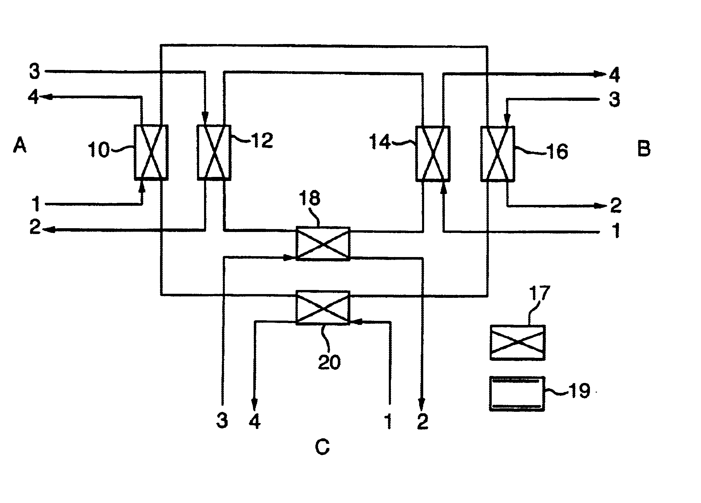
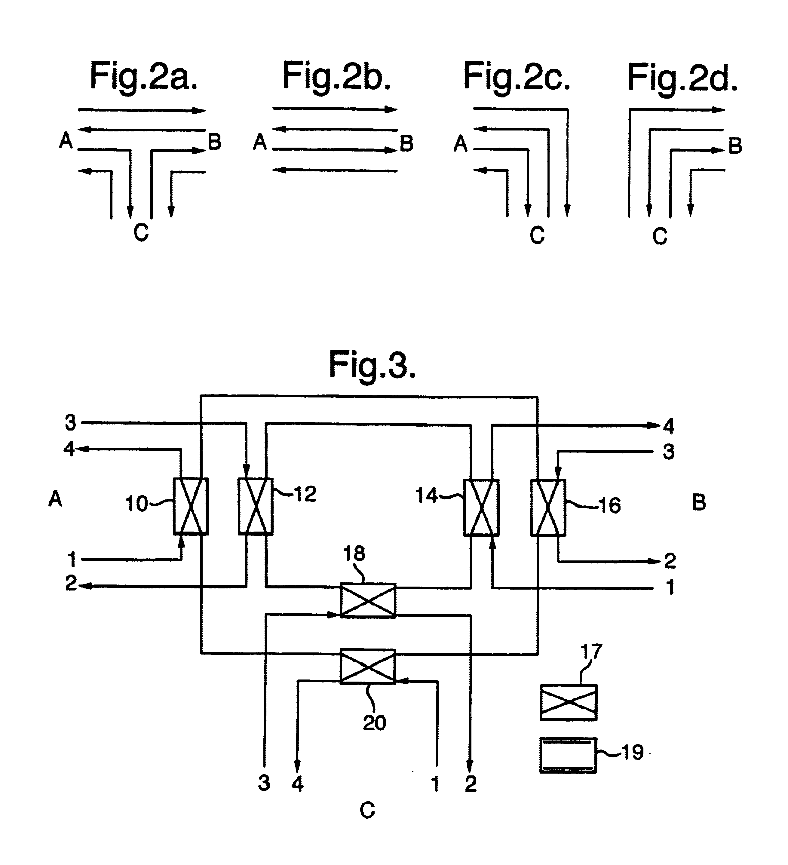
[0032]Referring now to FIG. 2, there is shown various possible routeings of a basic two-fibre-pair branching unit having branches A, B and C. In FIG. 2a there is shown a default configuration where one pair of inputs / outputs on branch A are optically routed directly to a first pair of corresponding output / inputs of branch B—the so-called fast data path for connection in the main data highway of a communication system. A second pair of inputs / outputs on branch A are optically routed to a corresponding first pair of output / inputs of branch C whilst branch C has a second pair of input / outputs which are routed to a corresponding second pair of output / inputs of branch B. This forms a so-called slow data path for communication between branch A and B via C.

[0033]The present invention seeks to permit optimal usage of the fibers in dependence upon traffic requirement and destinations and under fault conditions due to cable damage. In the event of no traffic requirement between A or B and C t...


PUM


Abstract

A branching unit, for use in optical communication systems, has three branches A, B and C each including a connection for a power feed and several inputs/outputs for optical fibers. Optical switches are provided for selectively coupling inputs/outputs of different branches to enable a routeing of optical signals through the unit. The routeing is effected in dependence upon the way in which each of the three branch connections are provided with an electrical power feed.

Description

BACKGROUND OF THE INVENTION[0001]This invention relates to a branching unit and system for underwater communication in which optical signals can be selectively routed between branches.[0002]Branching units for underwater optical communication systems normally have three branches and are normally arranged to through-couple one fibre pair connected to one branch to a fibre pair on another branch, which fibre pairs form a main highway for optical data signals. In order to route specific signals to a spur terminal connected to another branch such signals are propagated with a specific wavelength and can be diverted to the other branch by means of a wavelength division multiplex system (WDM) which also permits signals to be sent from the spur terminal and to be injected at the specific wavelength into the main highway. This system is effective but does not permit maximum usage of the optical capacity of the main highway if no traffic is required to or from the spur terminal and does not ...

Claims


Application Information

Patent Timeline
Patent Type & Authority Patents(United States)
IPC IPC(8): H04Q11/00H02J1/00H02G15/14H04B3/44H04B10/02H04B10/17H04B10/29
CPCH04Q11/0005H04Q2011/0052H04Q2011/0049H04Q2011/0007
Inventor WEBB, STEPHEN MICHAEL
Owner ALCATEL LUCENT SAS
Why Eureka
Try Eureka