
Screwdriver

a screwdriver and screw technology, applied in the direction of screwdrivers, power-driven tools, wrenches, etc., can solve the problems that the user of the known screwdriver may be in difficulty in continuously applying a pressing load onto the screwdriver during the screw tightening operation, and achieve the effect of preventing the transmission of torque and efficient transmission of torque for tightening the screw

Inactive Publication Date: 2005-05-17
MAKITA CORP
View PDF9 Cites 9 Cited by
  • Summary
  • Abstract
  • Description
  • Claims
  • Application Information

AI Technical Summary

Benefits of technology

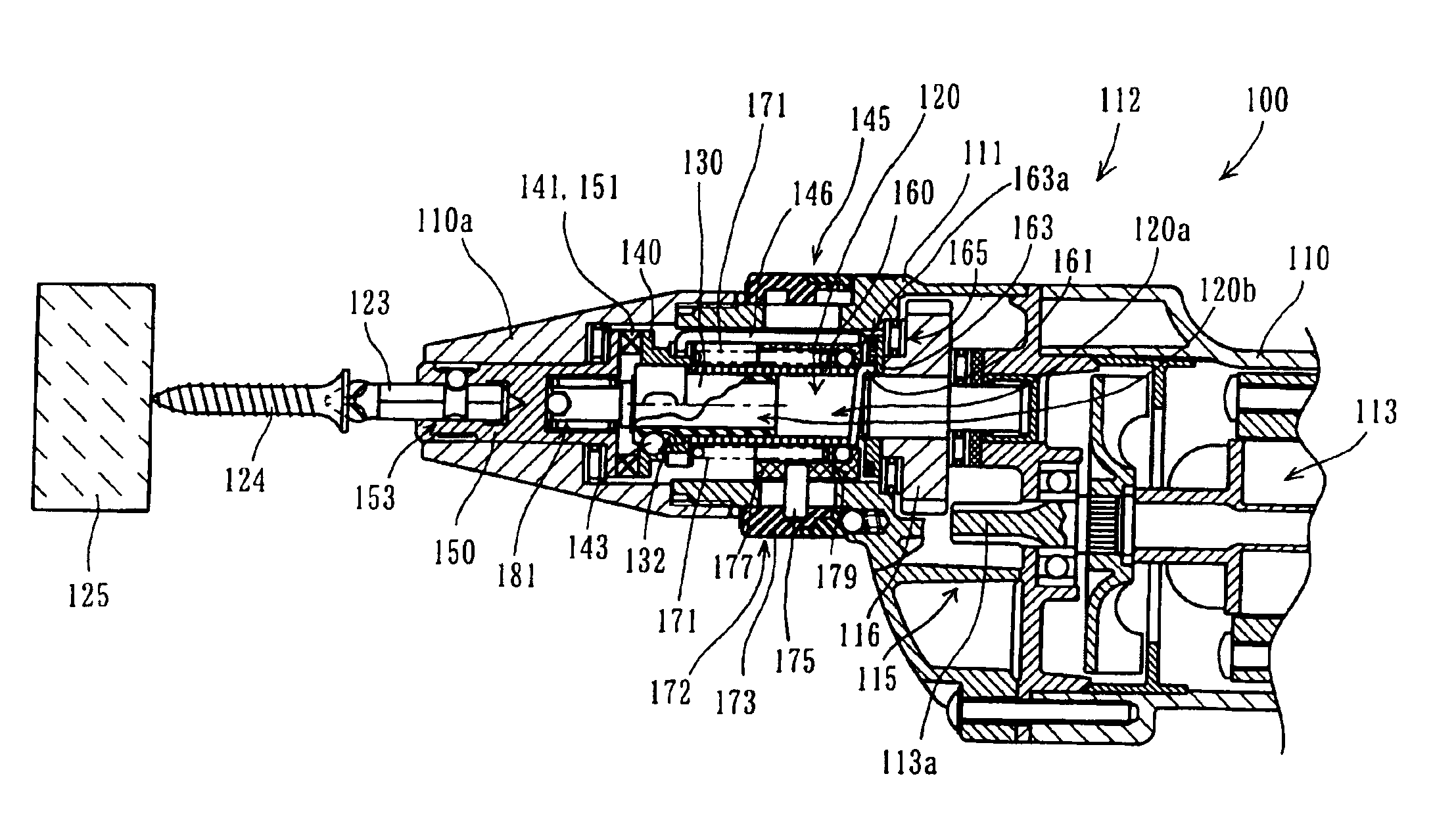
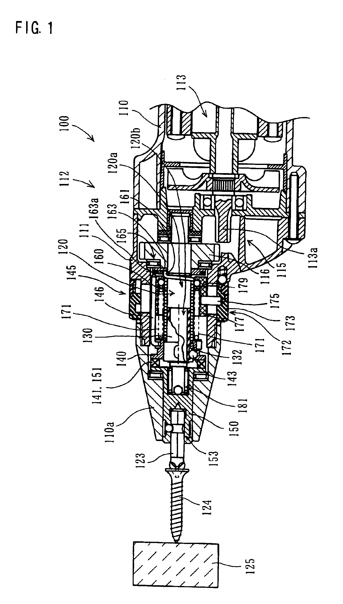
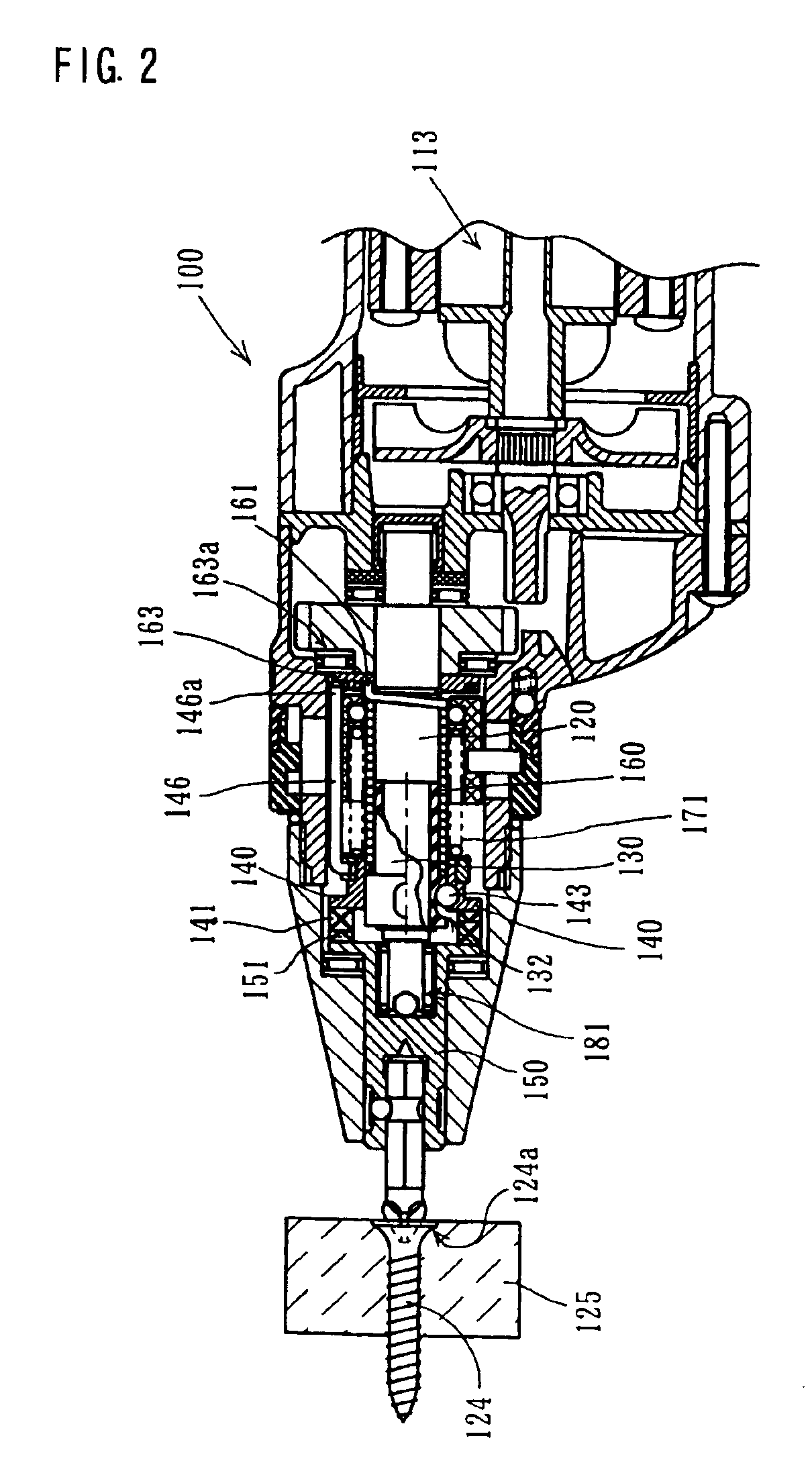
The present invention is an electric screwdriver that can efficiently transmit torque for tightening a screw and stop the torque transmission. It includes a motor, rotating members, a tool, a torque transmission spring, and a torque transmission releasing device. The torque transmission spring transmits the rotating torque of the motor from the first rotating member to the second rotating member in order to drive the tool. The torque transmission releasing device moves in response to the screw-tightening torque and releases the close winding of the torque transmission spring around at least one of the first rotating member and the second rotating member and stops the transmission of the rotating torque of the motor to the tool. The screwdriver can efficiently transmit torque for tightening a screw and stop the torque transmission.

Problems solved by technology

However, as for a screw such as a universal joint, which is tightened in a relatively narrow work area, the user of the known screwdriver may be in difficulty to continuously apply a pressing load onto the screwdriver during the screw tightening operation.

Method used


Image

  • Screwdriver
  • Screwdriver
  • Screwdriver

Examples


Embodiment Construction

[0014]According to the present teachings, a representative electric screwdriver may include a motor, a first rotating member, a second rotating member and a tool. The first rotating member is driven by the motor. An AC motor, a DC brushless motor or other various motors may be utilized as a motor. Preferably, the first rotating member may be connected to the motor via a speed reducing mechanism that utilizes for example planetary gears and so on. The second rotating member is adapted to rotate by receiving the rotating torque of the first rotating member.

[0015]The tool is drivingly rotated via the first rotating member and the second rotating member for screw-tightening operation. According to the present teachings, a torque transmission spring is used to transmit the rotating torque of the motor from the first rotating member to the second rotating member. The torque transmission spring closely winds around the first rotating member and the second rotating member when the motor is ...


PUM


Abstract

It is an object of the invention to provide an electric screwdriver that can efficiently transmit torque for tightening a screw and stop the torque transmission. A representative screwdriver may include a motor, first and second rotating members, a tool, a torque transmission spring and a torque transmission releasing device. The torque transmission spring transmits the rotating torque of the motor from the first rotating member to the second rotating member in order to drive the tool by closely winding around the first rotating member and the second rotating member when the motor drivingly rotates the first rotating member in a predetermined rotating direction. Further, the torque transmission releasing device moves in the axial direction of the first rotating member or the second rotating member in response to the screw-tightening torque. By such movement, the torque transmission releasing device releases the close winding of the torque transmission spring around at least one of the first rotating member and the second rotating member and releases the transmission of the rotating torque of the motor to the tool.

Description

BACKGROUND OF THE INVENTION[0001]The teachings of U.S. patent application Ser. No. 10 / 353,672, filed on Jan. 29, 2003, are herein incorporated by reference.[0002]1. Field of the Invention[0003]The invention relates to an electric screwdriver that can efficiently transmit torque for screw-tightening operation and release the torque transmission.[0004]2. Description of the Related Art[0005]An electric screwdriver is disclosed in unexamined Japanese laid-open patent publication No. 61-219581. The known screwdriver includes a silent clutch mechanism to connect a tool to a motor for transmitting the rotating torque of the motor to the tool. The silent clutch includes clutch members with clutch teeth that can be engaged with each other to transmit the motor torque to the tool. By utilizing the silent clutch mechanism, when the screw is tightened to a predetermined depth with respect to the workpiece, the clutch members can be promptly disengaged to stop transmission of the rotating torque...

Claims


Application Information

Patent Timeline
Patent Type & Authority Patents(United States)
IPC IPC(8): B25B23/14B25B21/00B25B23/155
CPCB25B23/141B25B23/14
Inventor SASAKI, KATSUHIKO
Owner MAKITA CORP
Learn More