Eureka AIR delivers breakthrough ideas for toughest innovation challenges, trusted by R&D personnel around the world.

Heat pipe having a wick structure containing phase change materials

a phase change material and heat pipe technology, applied in the direction of insulated conductors, cables, semiconductor/solid-state device details, etc., can solve the problems of heat pipe failure, sudden temperature rise outside the operating range, degradation or even failur

Inactive Publication Date: 2005-05-10
THERMAL
View PDF44 Cites 115 Cited by
  • Summary
  • Abstract
  • Description
  • Claims
  • Application Information

AI Technical Summary

Benefits of technology

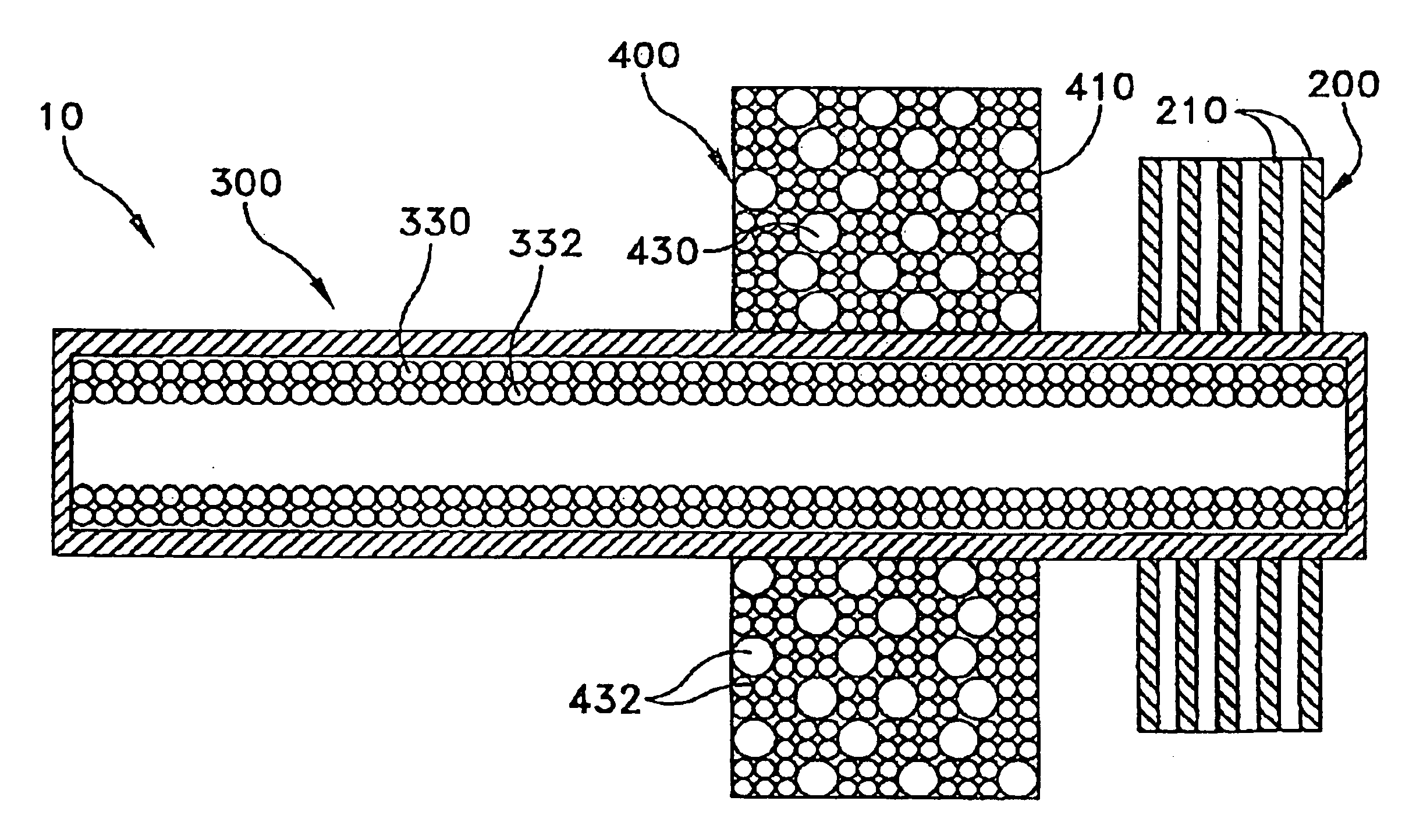
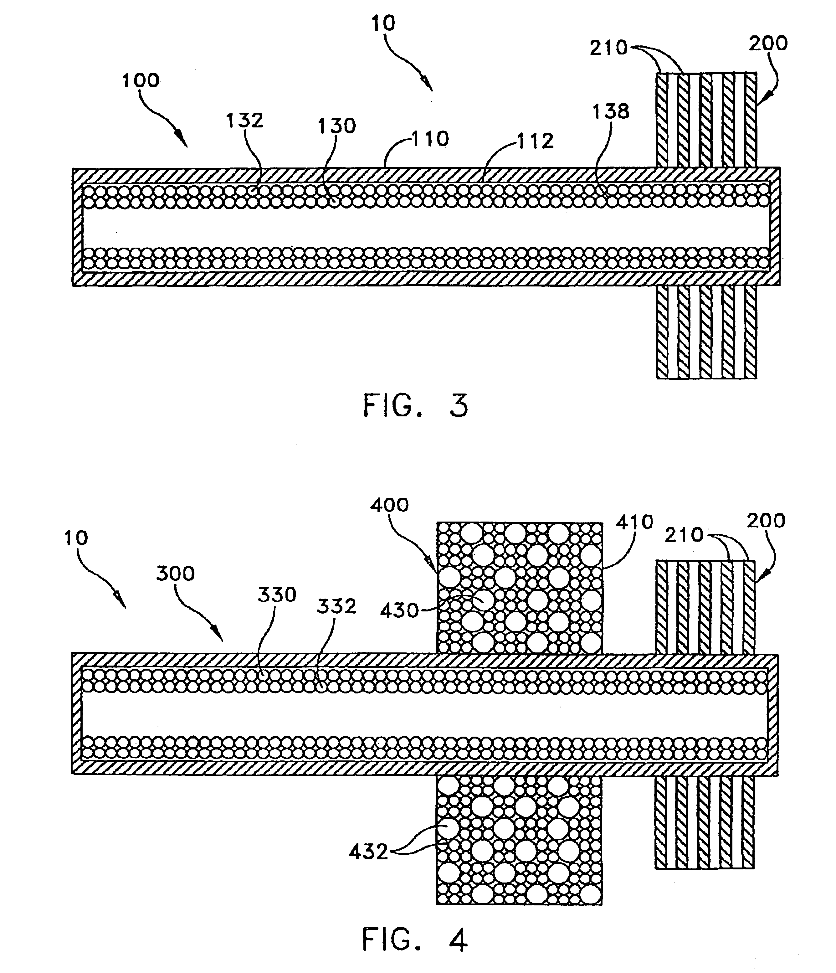
[0015]According to another aspect of the invention, the heat transfer device may include a first heat pipe and a second heat pipe having an envelope, a working fluid and a wick formed from or comprising micro-encapsulated PCM particles. The first heat pipe may be a conventional heat pipe or may have a wick comprised of micro-encapsulated PCM particles. The heat transfer device may further include a heat sink.

Problems solved by technology

However, operation outside of this range causes degradation or even failure.
Such a limitation is a disadvantage in applications where there may be peak loads which can cause a sudden temperature rise outside of the operating range of the heat pipe.
Not only can this cause failure of the heat pipe, but also may cause damage to the system which is being cooled.
Due to the increasingly high heat generated from these systems, and their proneness for transient peak loads, common heat transfer technologies such as heat sinks, cold plates, direct impingement cooling systems and conventional heat pipes are approaching their heat transfer limits.
This method has the disadvantage of needing an outside energy source to pump the heat transferring slurry.
They lack the advantage of having the heat released at a location distant from the heat source.

Method used


Image

  • Heat pipe having a wick structure containing phase change materials
  • Heat pipe having a wick structure containing phase change materials
  • Heat pipe having a wick structure containing phase change materials

Examples


Embodiment Construction

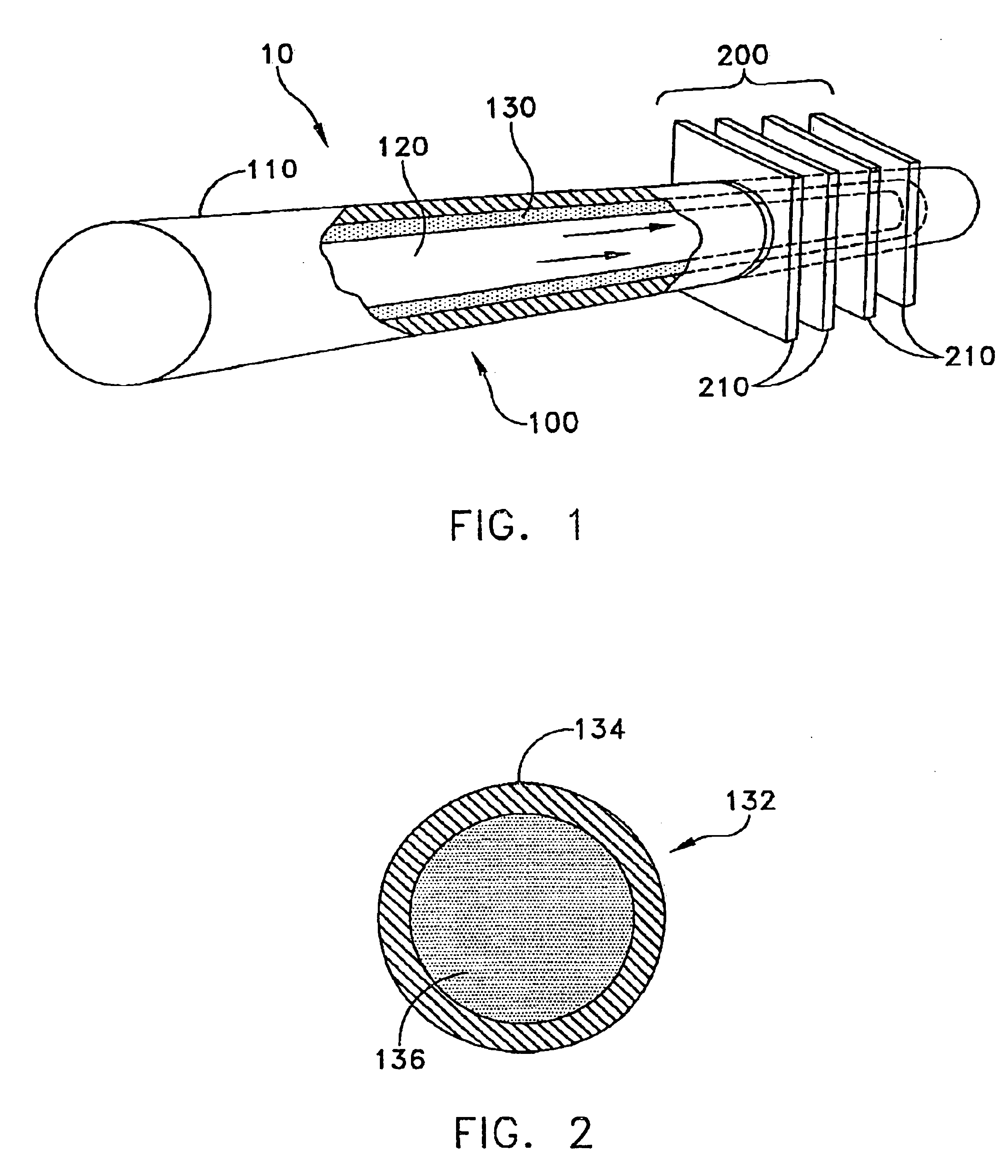
[0023]This description of preferred embodiments is intended to be read in connection with the accompanying drawings, which are to be considered part of the entire written description of this invention. The drawing figures are not necessarily to scale and certain features of the invention may be shown exaggerated in scale or in somewhat schematic form in the interest of clarity and conciseness. In the description, relative terms such as “horizontal,”“vertical,”“up,”“down,”“top” and “bottom” as well as derivatives thereof (e.g., “horizontally,”“downwardly,”“upwardly,” etc.) should be construed to refer to the orientation as then described or as shown in the drawing figure under discussion. These relative terms are for convenience of description and normally are not intended to require a particular orientation. Terms including “inwardly” versus “outwardly,”“longitudinal” versus “lateral” and the like are to be interpreted relative to one another or relative to an axis of elongation, or...


PUM


Abstract

A wick for use in a heat pipe is provided incorporating particles of micro-encapsulated phase change material bonded together to form the wick. Use of a wick structure comprising micro-encapsulated PCM particles has the advantage of providing an additional heat absorber. This greatly enhances the ability of the heat pipe to absorb excess heat and may help to prevent damage to the heat pipe or heat generating component, such as an electronic device, especially at times of peak thermal loads.

Description

FIELD OF THE INVENTION[0001]The present invention relates to heat pipes for heat dissipation, and more particularly, to heat pipes having a wick structure comprised of micro-encapsulated phase change materials.BACKGROUND OF THE INVENTION[0002]Heat pipes are highly efficient devices for transferring large quantities of heat from a heat source to an area where the heat can be dissipated. A heat pipe generally consists of a vacuum tight envelope, a wick structure and a working fluid. The heat pipe is evacuated and then back-filled with a small quantity of working fluid, typically just enough to saturate the wick. The atmosphere inside the heat pipe is set by an equilibrium of liquid and vapor. As heat enters at the evaporator, this equilibrium is upset generating vapor at a slightly higher pressure. This higher pressure vapor travels to the condenser end where the slightly lower temperatures cause the vapor to condense giving up its latent heat of vaporization. The condensed fluid is t...

Claims


Application Information

Patent Timeline
Patent Type & Authority Patents(United States)
IPC IPC(8): F28D15/04H01L23/427H01L23/34F28D20/02
CPCF28D15/046F28D20/023H01L23/427H01L23/4275H01L2924/0002Y02E60/145H01L2924/00Y02E60/14
Inventor ZUO, JONERNST, DONALD M.
Owner THERMAL
Why Eureka
Eureka Blog
Learn More