
Laser diode bar integrator/reimager

a technology of integrators and diodes, applied in the field of laser diodes, can solve the problems of limited usefulness of low power densities of these devices, and achieve the effects of improving balancing of optical invariants, reducing power density, and improving irradian

Active Publication Date: 2005-05-03
MEMS OPTICAL
View PDF4 Cites 18 Cited by
  • Summary
  • Abstract
  • Description
  • Claims
  • Application Information

AI Technical Summary

Benefits of technology

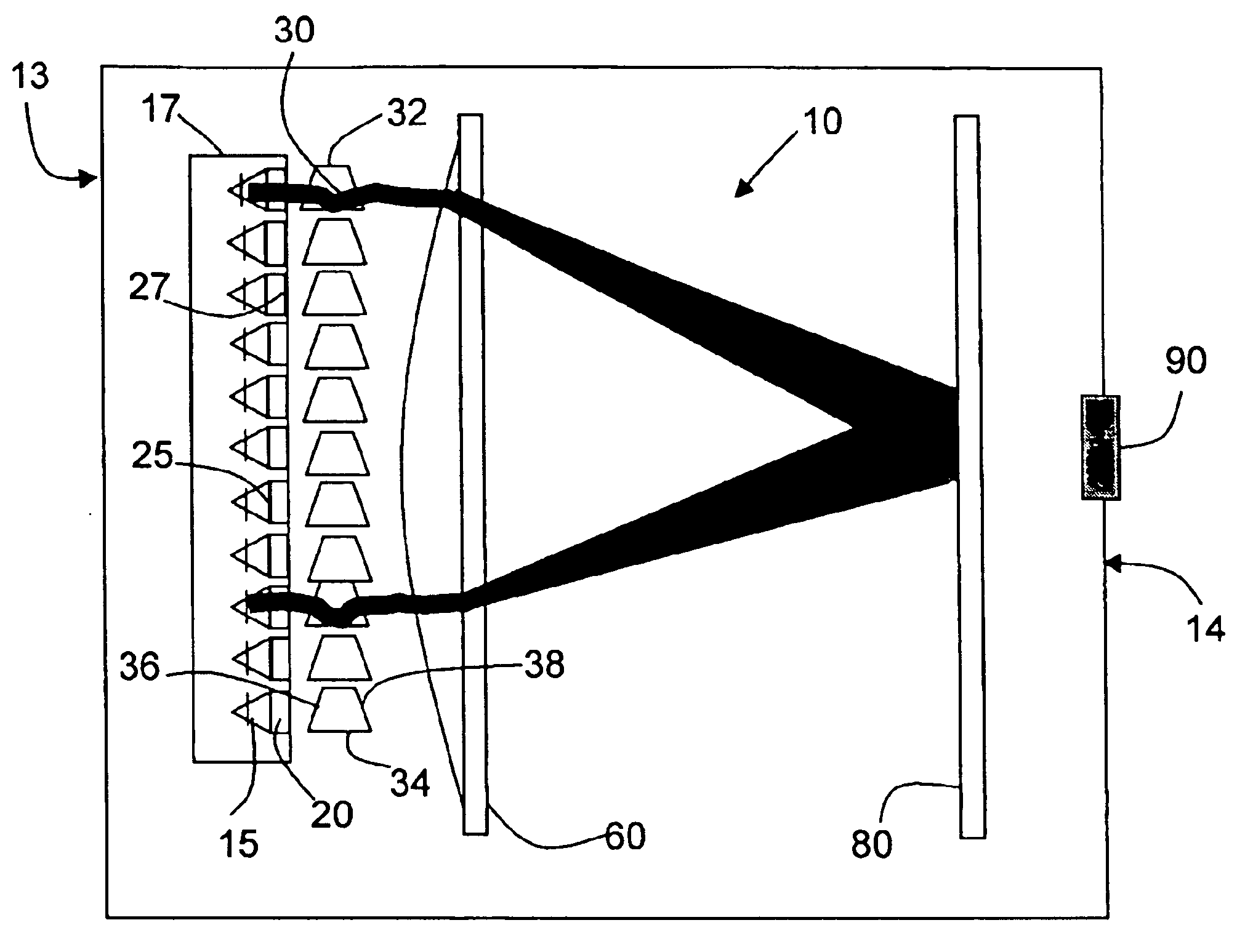
[0010]Further exemplary embodiments of the invention provides a lens (e.g. anamorphic lens) or array of lenses (e.g. an array of anamorphic lenses) to reshape an incident laser beam profile(s) in the fast and slow axis directions into desired laser beam profile(s). The invention provides a multi-beam integrator system, which is used along with a means of optically rotating the emitters by an angle (e.g. 90 degrees). The angle rotation allows for better balancing of the optical invariants in the slow and fast axis directions, making it easier to “circularize” the image for coupling into fibers or to increase the irradiance for laser machining applications. Furthermore, the present invention includes a lens (e.g. anamorphic lens) to achieve a nearly circular beam along with providing a significant increase in irradiance.
[0011]The invention and the methods derived thereof effectively reduce the source size so that one can achieve greater collimation and energy density.

Problems solved by technology

Since the advent of low-cost laser diodes, their inherently low power densities have limited the usefulness of these devices.
Using the laser diode light directly in laser machining and product marking could increase the efficiency and reduce the cost for such systems, but has proven to be a challenge due to the low average brightness or radiance of diode bar arrays.
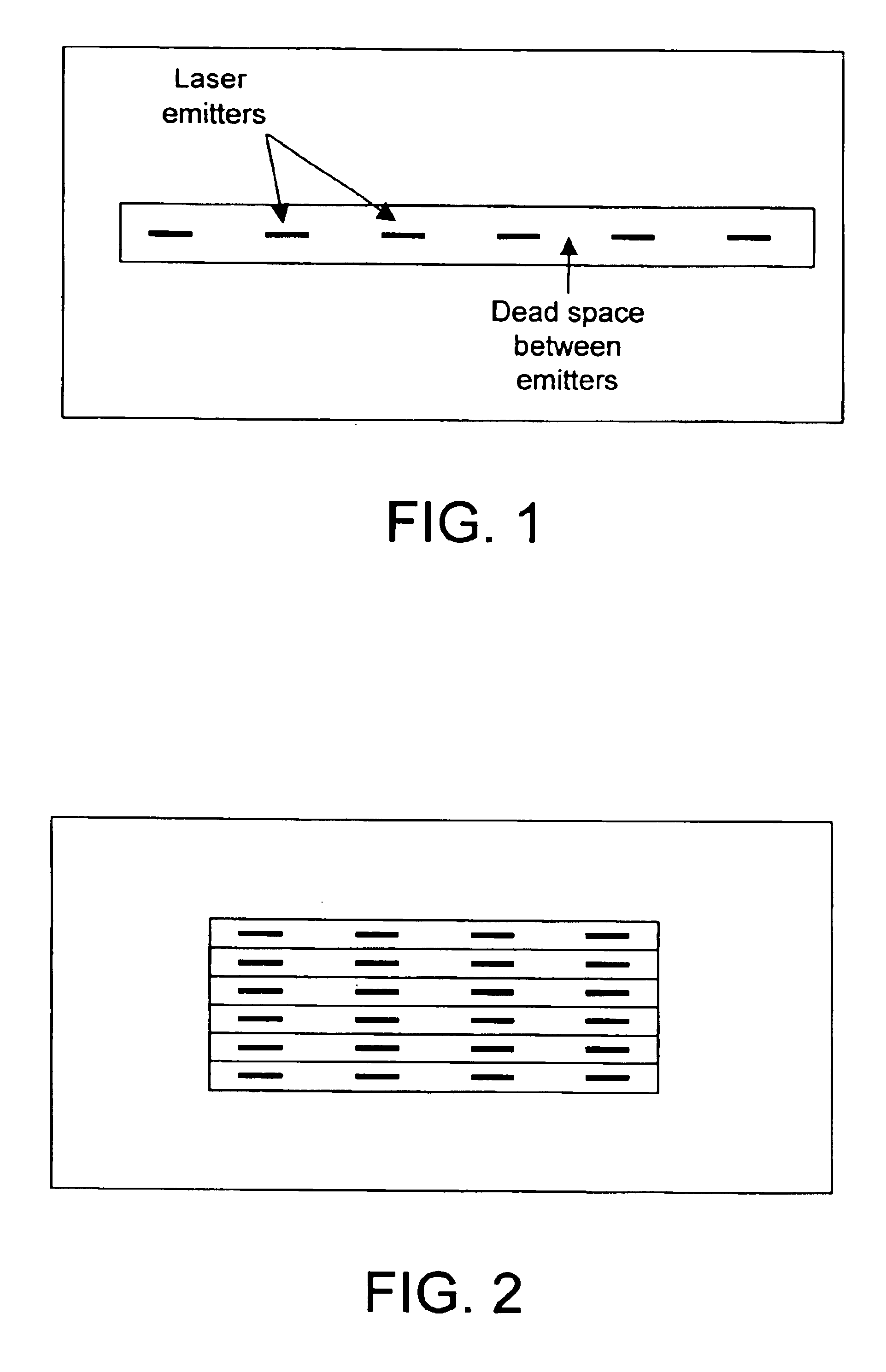
Due to the soldering process, the emitter spacing is not nearly as uniform as that of FIG. 1, and thus is not conductive to coupling with microlens arrays for beam integration.

Method used


Image

  • Laser diode bar integrator/reimager
  • Laser diode bar integrator/reimager
  • Laser diode bar integrator/reimager

Examples


Embodiment Construction

[0021]Exemplary embodiments of the invention can be used to increase the average source radiance and decrease the source size of a laser diode bar , comprised of an array of emitters, by optically reimaging and combining the emitters in such a way as to remove or reduce the non-emitting space between adjacent emitters and by optionally applying nonsymmetric (anamorphic) magnification to the superimposed image.

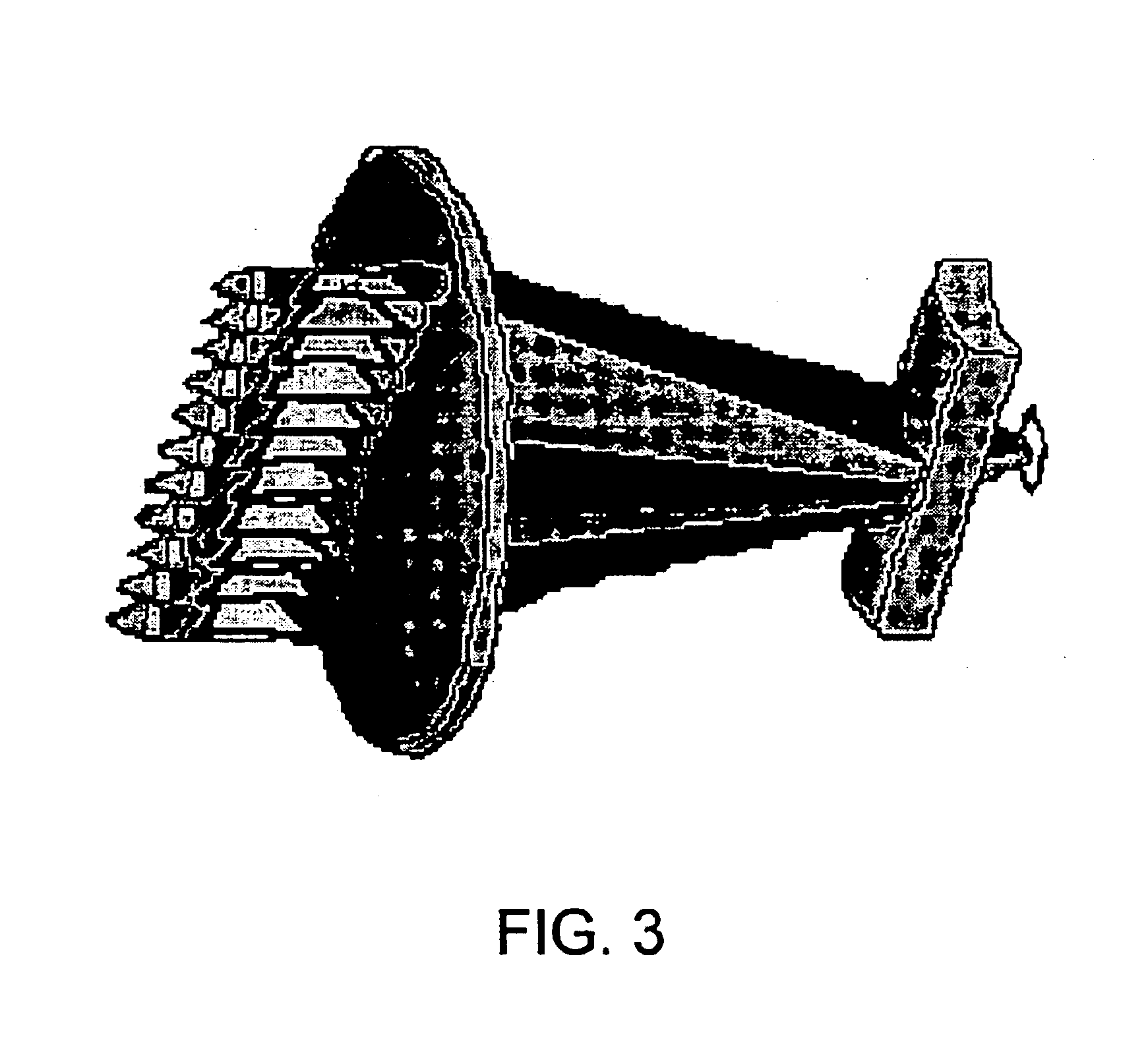
[0022]An exemplary embodiment of the invention, the multiple emitters of a laser diode bar configuration are reimaged and superimposed into a single emitter image with much smaller length so that the irradiance is increased and the image dimensions are more nearly equal in the orthogonal directions. If this image were reimaged to infinity, good collimation could be achieved in both the slow and fast axis directions of the emitter. A device produced in accordance with exemplary embodiments of the invention optically removes the non-emitting space between the emitters so that the...


PUM


Abstract

A beam integrator system, which integrates multiple beams into fewer beams of increased intensity by using a combination of optical elements and lenses.

Description

CORRESPONDING APPLICATIONS[0001]This application is a utility application, which is a conversion of provisional No. 60 / 427,571, filed 20 Nov. 2002, the entire contents of which are incorporated in their entirety.FIELD OF THE INVENTION[0002]The present invention relates to a method, apparatus and system for combining and integrating the multiple laser beams of a laser diode bar into fewer beam(s).BACKGROUND OF THE INVENTION[0003]Since the advent of low-cost laser diodes, their inherently low power densities have limited the usefulness of these devices. Various combinations of lenses and other optical devices have been used to combine multiple laser diode beams into fewer beams (e.g., a single beam) to increase power density. More commonly, multiple laser diodes or laser diode bar arrays simply serve as optical pumps for solid state lasers, rather than using their light directly in the laser machining or other high power laser process.[0004]Using the laser diode light directly in lase...

Claims


Application Information

Patent Timeline
Patent Type & Authority Patents(United States)
IPC IPC(8): G02B27/10G02B27/12G02B27/14G02B27/09H01S5/00H01S5/40
CPCG02B19/0028H01S5/4031G02B19/0057H01S5/4025H01S5/005H01S5/4012
Inventor BROWN, DANIEL M.
Owner MEMS OPTICAL
Learn More