Tolerance compensating mounting device

a technology of tolerating and mounting devices, which is applied in the direction of screws, washers, gearing, etc., can solve the problems of affecting the assembly of equipment components, unable to always be eliminated, and creating significant dimensional deviations or gaps

Inactive Publication Date: 2005-04-26
THE GATES CORP
View PDF13 Cites 41 Cited by
  • Summary
  • Abstract
  • Description
  • Claims
  • Application Information

AI Technical Summary

Benefits of technology

[0010]The primary aspect of the invention is to provide a tolerance compensating mounting device that completely compensates for a tolerance gap or assembly clearance between components to be joined using a threaded bushing while simultaneously connecting the components.
[0011]Another aspect of the invention is to provide a tolerance compensating mounting device that completely compensates for a tolerance gap between components to be joined using a threaded fastener.

Problems solved by technology

Assembly of equipment components can be adversely affected by tolerances, that is, dimensional differences between components that may result in gaps at fastening points.
They cannot always be eliminated, but only allowed for in the assembled device.
Tolerances can also “stack” when more than two components are joined at a particular location, creating a significant dimensional deviation or gap.
The prior art does not solve the problem of compensating for tolerances between planar mounting surfaces while simultaneously joining the components in a properly torqued or clamped manner; all without inducing undesirable stresses in the components.
Nor does the prior art allow a component having non-coplanar connecting surfaces to be properly joined.
Nor does the prior art provide a fastener that automatically compensates for a tolerance gap or clearance between mounting surfaces as part of the assembly process.

Method used


Image

  • Tolerance compensating mounting device
  • Tolerance compensating mounting device
  • Tolerance compensating mounting device

Examples


Embodiment Construction

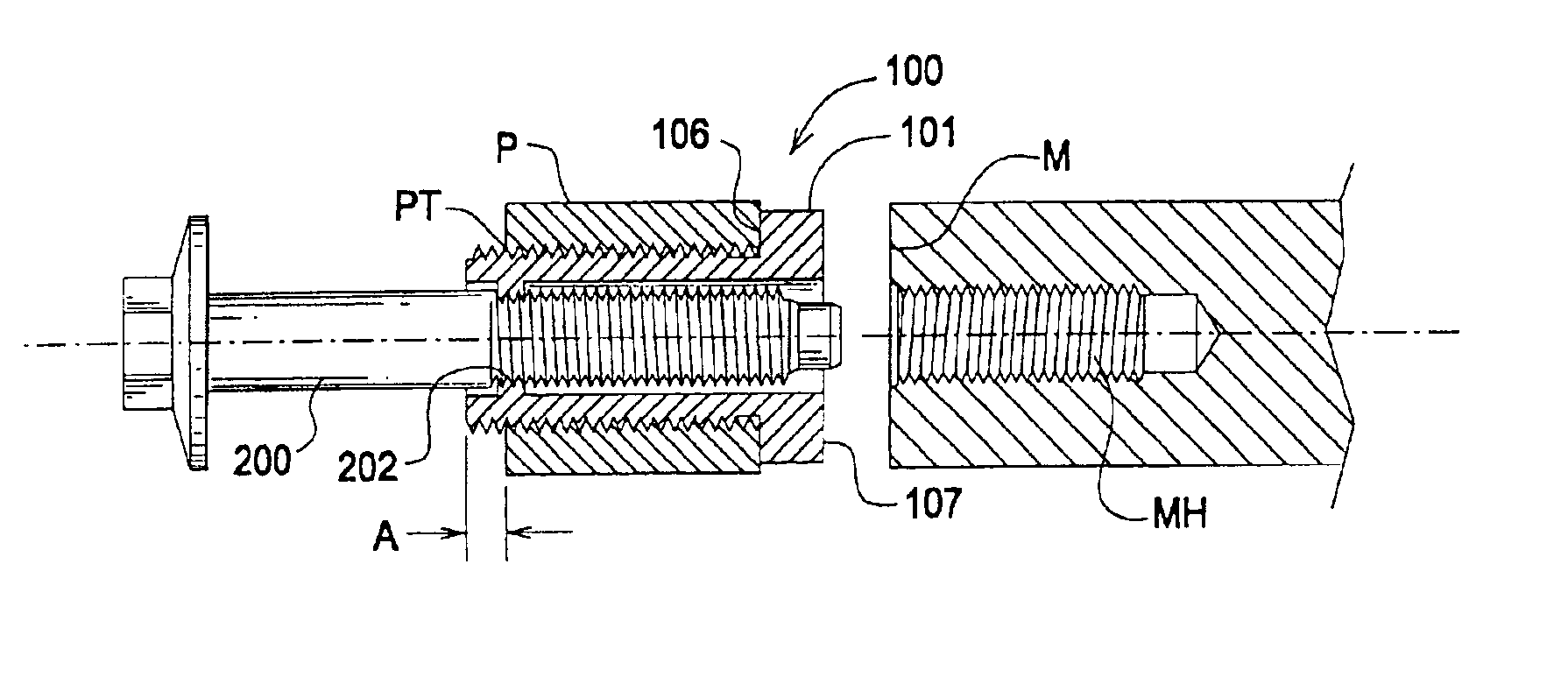
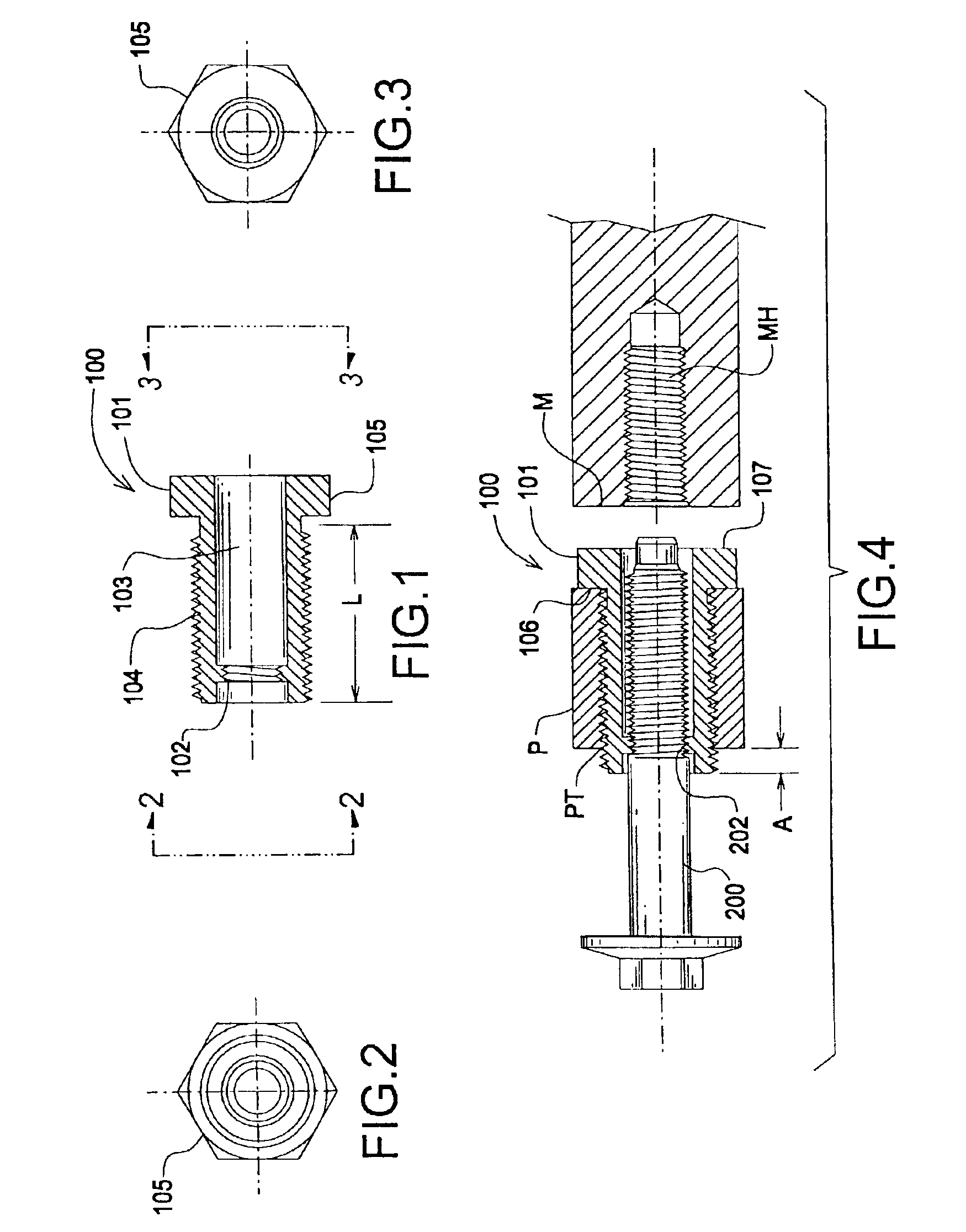
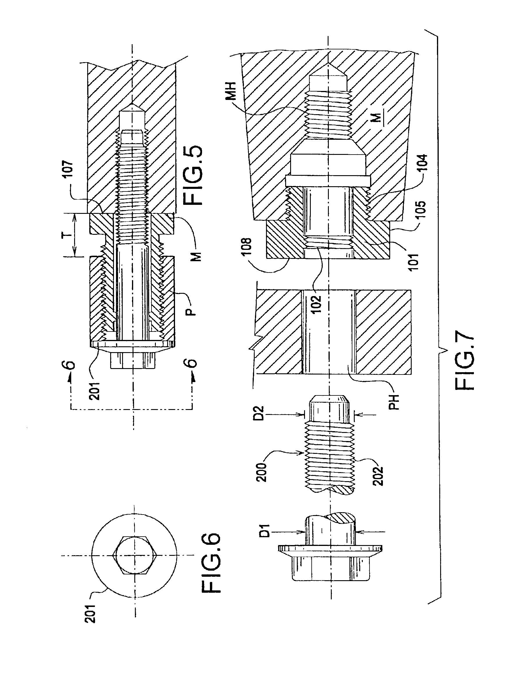
[0031]FIG. 1 is a cross-section view of the tolerance compensating mounting device. The inventive device 100 comprises bushing 101. Bushing 101 is substantially cylindrical. Bushing 101 having a surface feature 102 comprising a thread. Surface feature 102 may comprise raised potions of the surface for engaging a fastener as described herein. In the preferred embodiment surface feature comprises thread 102.

[0032]Thread 102 comprises approximately two pitches of any thread form known in the art. Bushing 101 also comprises bore or hole 103 that runs the length of bushing 101 along a major axis. Bolt 200 engages bushing 101 through hole 103. Bolt 200, see FIG. 4, engages threads 102. An internal minor diameter of threads 102 is less than an internal diameter of hole 103 such that threads 102 may engage a bolt without bolt 200 engaging a surface of hole 103.

[0033]Bushing 101 comprises a metallic material on the preferred embodiment. However, one can appreciate that it may also comprise a...


PUM


Abstract

The invention comprises a tolerance compensating mounting device comprising a bushing having an internal and external thread. The bushing is threaded into a part to be mounted to a surface. A bolt is then threaded into a bushing bore using the internal threads. The internal threads cause an interference fit between the bolt shank and the threads, temporarily preventing further insertion of the bolt. The bolt is then turned further, thereby turning the bushing and causing the bushing to unscrew from the part toward the mounting surface until the bushing seats on the mounting surface, thereby completely compensating for a tolerance gap. As the bolt is turned further, at a relatively low torque the sacrificial internal threads are stripped allowing the bolt to be fully torqued into the mounting surface hole, thereby simultaneously connecting the components with a properly torqued connection while compensating for a tolerance gap.

Description

REFERENCE TO RELATED APPLICATIONS[0001]This application is a continuation-in-part of and claims priority from U.S. application Ser. No. 09 / 840,265 filed Apr. 23, 2001, now abandoned.FIELD OF THE INVENTION[0002]The invention relates to a fastening device, and more particularly, to a tolerance compensating mounting device used to connect components while compensating for a fit tolerance between the components.BACKGROUND OF THE INVENTION[0003]Assembly of equipment components can be adversely affected by tolerances, that is, dimensional differences between components that may result in gaps at fastening points. They cannot always be eliminated, but only allowed for in the assembled device. Tolerances can also “stack” when more than two components are joined at a particular location, creating a significant dimensional deviation or gap.[0004]Tolerances may be very small, fractions of a millimeter, or very large, several millimeters, depending upon the circumstances. Larger tolerances gene...

Claims


Application Information

Patent Timeline
Patent Type & Authority Patents(United States)
IPC IPC(8): F16B5/02F16B29/00F16H1/00F16B43/00
CPCF16B5/0233F16B5/025Y10S411/97F16B29/00Y10S411/999F16B5/0283F16B5/02
Inventor STONE, ROGERKNIGHT, BRIAN RUSSELL
Owner THE GATES CORP
Why Eureka
Try Eureka