
Optical spacer switch and insertion head, automatic insertion machine and method for inserting components on substrates by using the optical spacer switch

an automatic insertion machine and optical spacer switch technology, applied in the direction of optics, optical elements, instruments, etc., can solve the problems of reducing the positioning accuracy that can be achieved, increasing the susceptibility of the gripper as well as its mass, and affecting the insertion accuracy of the automatic insertion machine. , to achieve the effect of increasing the insertion capacity of the automatic insertion machin

Inactive Publication Date: 2005-04-19
ASMPT GMBH & CO KG
View PDF14 Cites 3 Cited by
  • Summary
  • Abstract
  • Description
  • Claims
  • Application Information

AI Technical Summary

Benefits of technology

[0009]An object of an embodiment of the invention is to create a compact and lightweight spacer switch for effecting a quick distance determination, an insertion head, as well as an automatic insertion machine, designed to permit a high insertion of components on substrates with a simultaneously low failure rate. It is furthermore an object of an embodiment of the invention to create a method for inserting components onto substrates which makes it possible to have a low failure rate due to damaged components, damaged gripping devices and / or damaged substrates along with a high insertion rate.
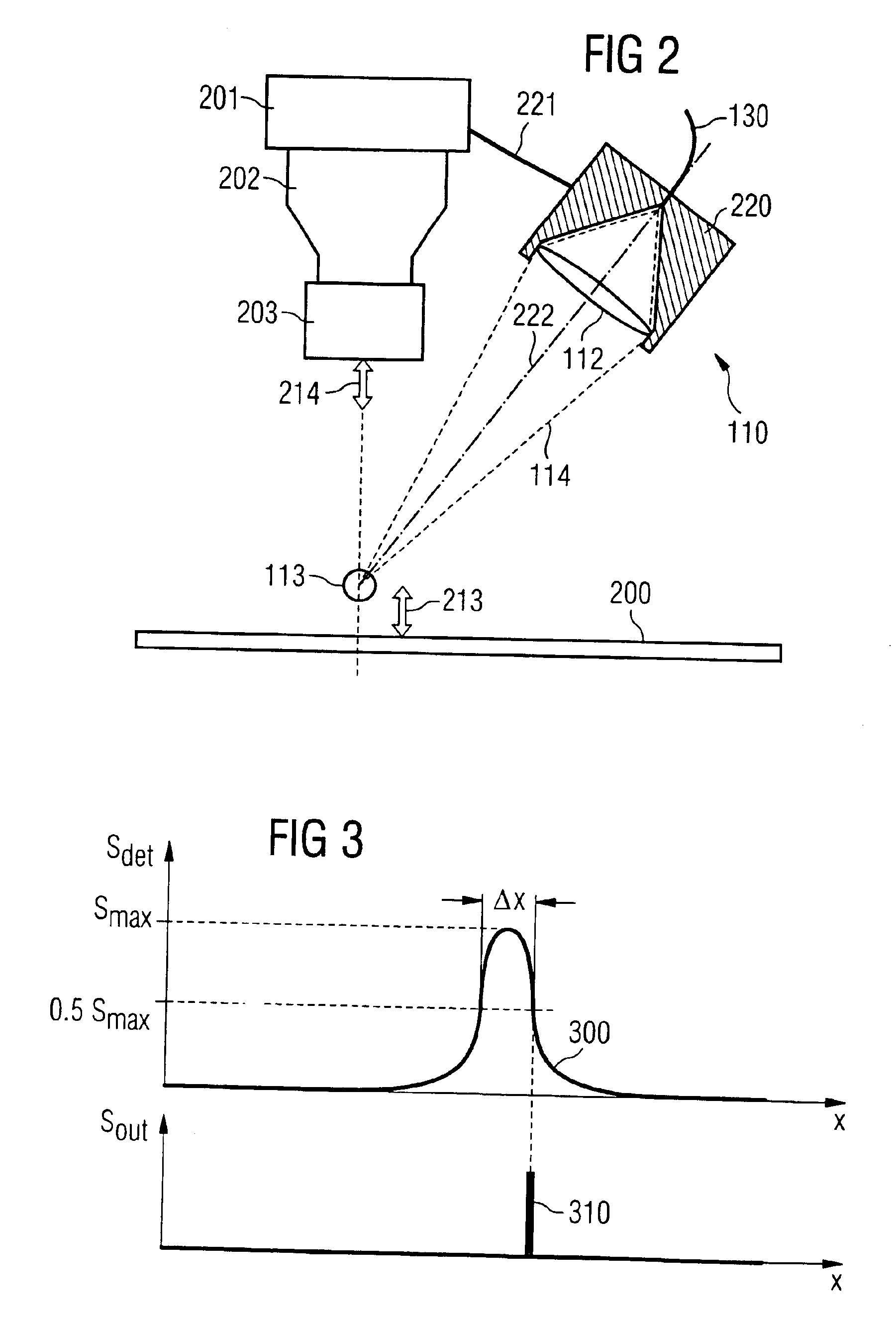
[0011]The course of the light intensity, which is reflected or scattered back to the light-receiving element by an object entering the switching range, may initially be described qualitatively. For this, it must be assumed that the object to be detected is initially far outside of the switching range. In that case, the intensity of the light scattered back to the light-receiving element is very low. During the approach of the object to the switching range, the intensity that is reflected back and imaged on the light-receiving element increases. This intensity reaches a maximum if the surface of the object to be examined is located exactly in the central region of the switching range. During a further approach of the object to be detected to the optical spacer switch, the object surface that scatters back the light initially leaves the central region of the switching range and subsequently the complete switching range and the intensity detected by the light-receiving element consequently decreases once more. This results in the ability to determine precisely when a switching signal is emitted, meaning at which distance between the optical switch and the object triggering the switching operation. Accordingly, the signal is triggered precisely at the point in time where the course of the scattered back light intensity falls below a specific threshold value after exceeding a maximum intensity value.

Problems solved by technology

The components for insertion, which are suspended vertically from the top by the suction pipettes, can be damaged, for example, through a high impact when they are place with excessive speed onto the substrates.
This solution increases the susceptibility of the gripper as well as its mass and reduces the positioning accuracy that can be achieved.

Method used


Image

  • Optical spacer switch and insertion head, automatic insertion machine and method for inserting components on substrates by using the optical spacer switch
  • Optical spacer switch and insertion head, automatic insertion machine and method for inserting components on substrates by using the optical spacer switch
  • Optical spacer switch and insertion head, automatic insertion machine and method for inserting components on substrates by using the optical spacer switch

Examples


Embodiment Construction

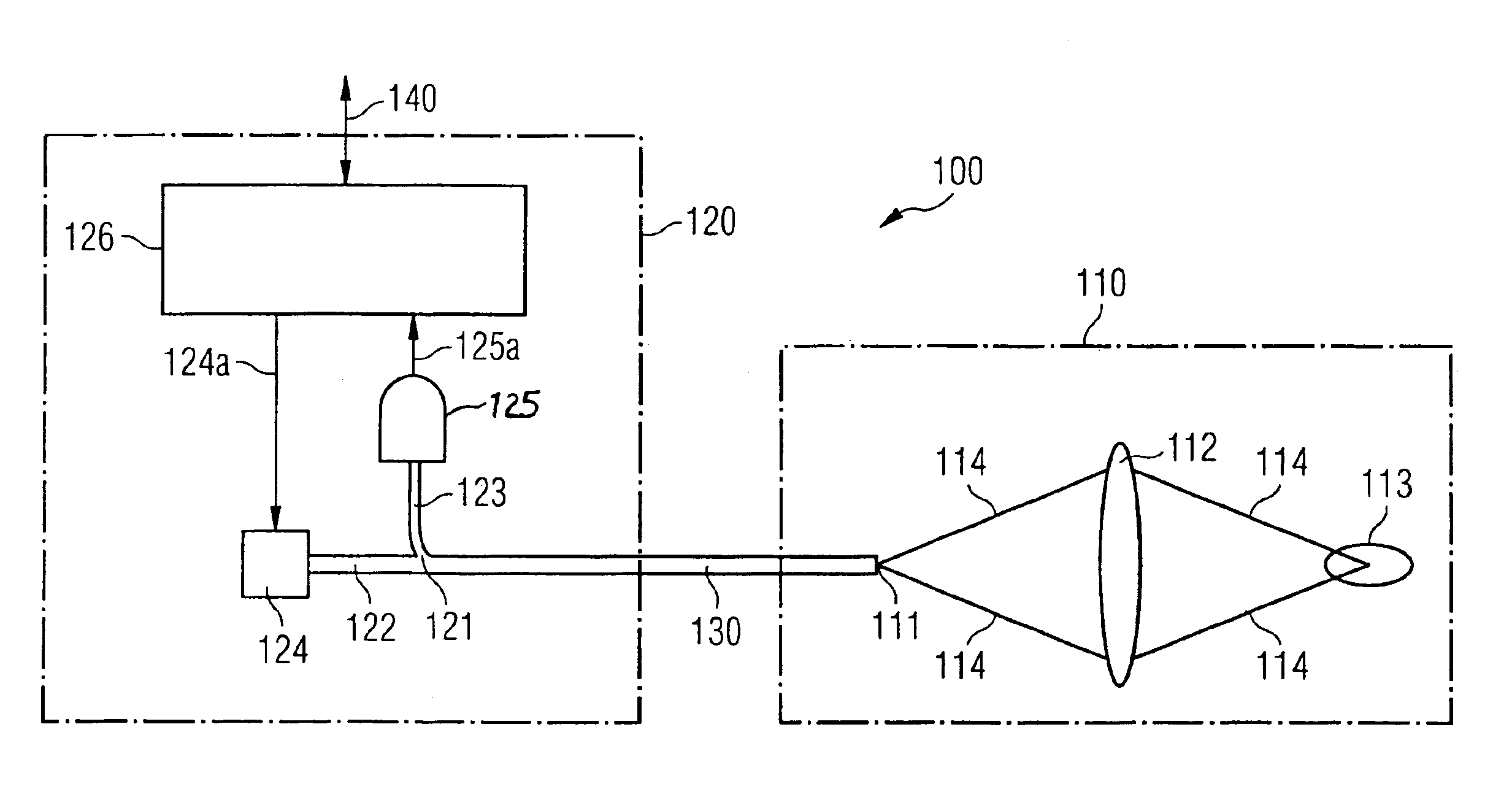
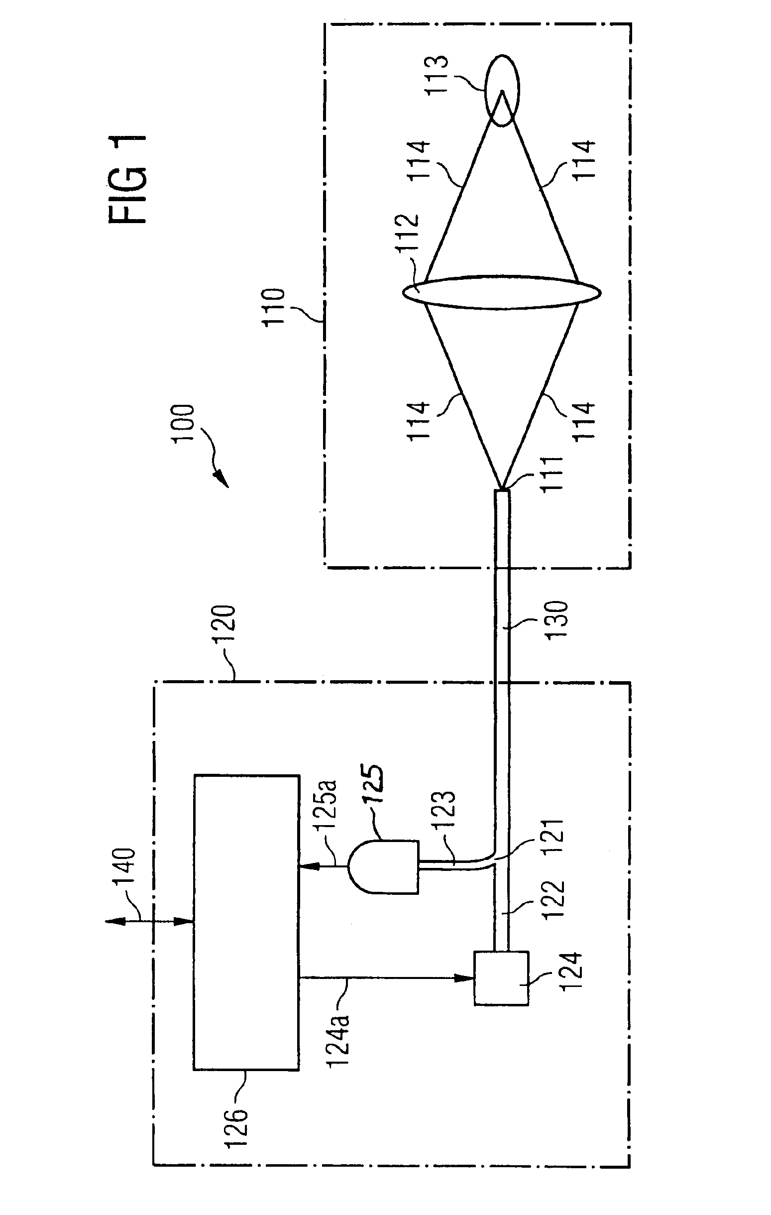
[0028]FIG. 1 shows that an optical spacer switch 100 is divided into two spatially separate modules, an optical module 110 and an electro-optical module 120. The two spatially separated modules are connected via an optical waveguide 130, preferably a so-called mono-mode optical waveguide. The optical module 110 has a fiber end 111 that simultaneously functions as nearly point-shaped light-emitting element and as nearly point-shaped light-receiving element. An image of the light emitted by the fiber end 111 is formed by the imaging optics 112 on a switching range 113. The edge rays of the respective light bundle are given the reference number 114 in FIG. 1. For the electro-optical module 120, the other fiber end of the optical waveguide 130 is split into two partial ends, a first partial end 122 and a second partial end 123. The division according to the embodiment in FIG. 1 occurs with a three-way optical waveguide coupler 121. The first partial end 122 of the optical waveguide 130 ...


PUM


Abstract

A confocal spacer switch for a fast, non-contacting determination of the spacing includes a point-shaped element that simultaneously transmits and receives light, imaging optics that form an image of the light-emitting element on a switching range and a light detection device that is coupled to the light-receiving element and emits a signal if an at least partially reflecting object enters the switching range and reflected light falls onto on the light-receiving element. The light-emitting and the light-receiving element preferably is realized with an optical waveguide end. As a result, the optical spacer switch can be divided into two modules that are connected via the optical waveguide, wherein a purely optical module can be realized in a compact and lightweight manner. A method for inserting components on substrates, uses the spacer switch, for which the insertion speed of the components is reduced immediately prior to inserting them. Thus, the impact of the component with the substrate is reduced, for an on the whole fast insertion operation.

Description

[0001]The present application hereby claims priority under 35 U.S.C. §119 on German patent publication number DE 10145167.9 filed Sep. 13, 2001, the entire contents of which are hereby incorporated herein by reference.FIELD OF THE INVENTION[0002]The invention generally relates to an optical spacer switch for the fast and non-contacting determination of spacing. Preferably, this is based on the confocal imaging (image-forming) principle as well. The invention further generally relates to an insertion head and an automatic insertion machine for inserting components on substrates by using the optical spacer switch. The invention furthermore generally relates to a method for inserting components on substrates by using the optical spacer switch.BACKGROUND OF THE INVENTION[0003]For the automatic insertion of components on circuit boards, the components are withdrawn from a pick-up location on a component feeding device by using a gripping device and are transported to the component insert...

Claims


Application Information

Patent Timeline
Patent Type & Authority Patents(United States)
IPC IPC(8): G01B11/02G01B11/14H01L31/12
CPCG01B11/026
Inventor HAAS, GERHARDSCHICK, ANTON
Owner ASMPT GMBH & CO KG
Learn More