Magnetic recording/reproducing device

a recording device and magnetic technology, applied in the field of magnetic recording/reproducing devices, can solve the problems of difficult determination and difficulty in increasing a two-dimensional size, and achieve the effects of easy stabilization of the rotation of the worm gear, and high durability

Inactive Publication Date: 2005-04-19
PANASONIC CORP
View PDF4 Cites 0 Cited by
  • Summary
  • Abstract
  • Description
  • Claims
  • Application Information

AI Technical Summary

Benefits of technology

[0022]Thus, the invention described herein makes possible the advantages of providing: (1) a magnetic recording / reproducing device which includes a thrust bearing mechanism capable of easily stabilizing the rotation of a worm gear; (2) a magnetic recording / reproducing device which includes a thrust bearing mechanism capable of easily stabilizing the rotation of a worm gear and being used with a compact magnetic recording / reproducing device; (3) a magnetic recording / reproducing device which includes a cost-efficient, high-durability and creep-resistant thrust bearing mechanism capable of increasing the degree of freedom for material selection and easily stabilizing the rotation of a worm gear; and (4) a magnetic recording / reproducing device which includes a thrust bearing mechanism capable of increasing deflection of a worm gear member, facilitating adjustments for dimensional unevenness and easily stabilizing the rotation of the worm gear.

Problems solved by technology

However, in the conventional speed reducer 400, it is difficult to determine these parameters for setting for force F4 generated by the worm gear bearing 4 so as to stabilize the rotation of the worm gear 3 under the above-described condition.
Specifically, as magnetic recording / reproducing devices become more compact, there is difficulty in increasing a two-dimensional size, i.e., the length L, width W, etc., of the worm gear bearing 4.

Method used


Image

  • Magnetic recording/reproducing device
  • Magnetic recording/reproducing device
  • Magnetic recording/reproducing device

Examples


example 1

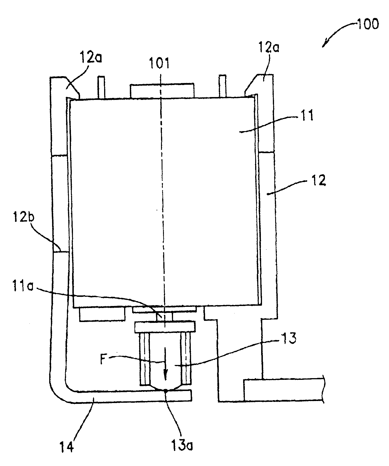
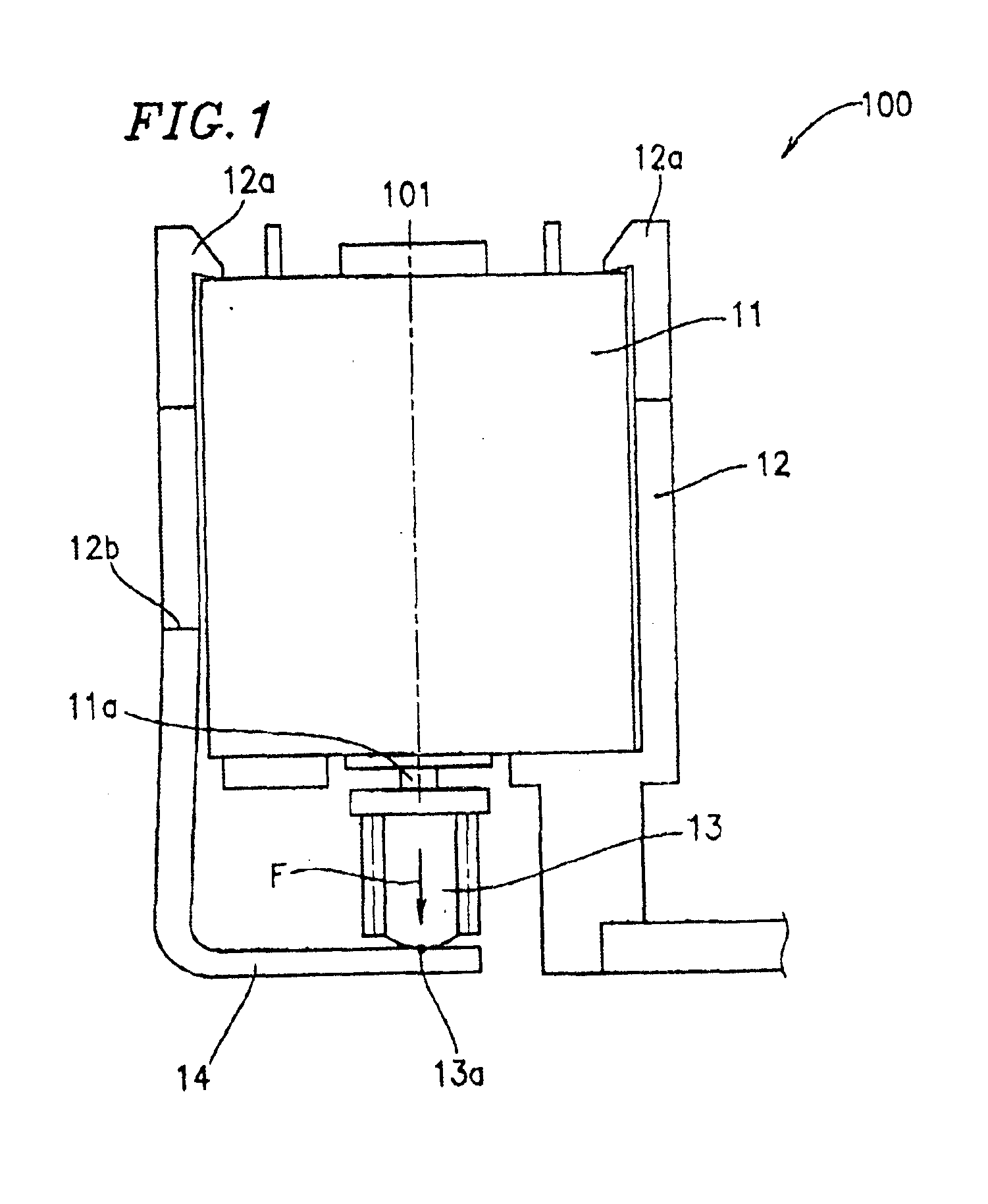
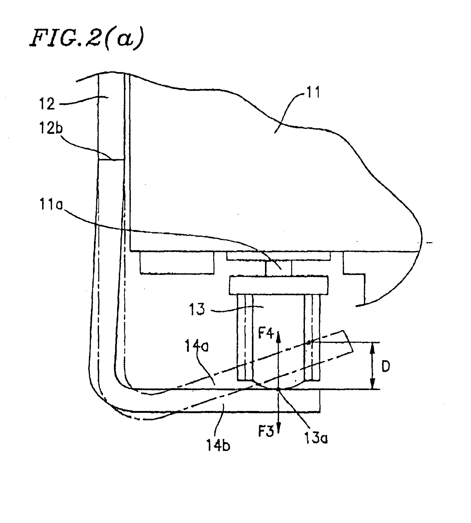
[0033]FIG. 1 is a structural view of a loading motor section of a speed reducer 100 of a magnetic recording / reproducing device according to Example 1 of the present invention. FIGS. 2(a)-(c) are magnified views each illustrating a part of the loading motor section of the speed reducer of the magnetic recording / reproducing device of FIG. 1. FIG. 3 is a view for explaining the shape and size of a thrust bearing mechanism of the speed reducer of the magnetic recording / reproducing device of FIG. 1.

[0034]In FIG. 1, the speed reducer 100 includes a loading motor 11, a loading motor shaft 11a, a holder 12, a worm gear 13 and a worm gear bearing 14. The loading motor 11 is coupled to the loading motor shaft 11a so as to rotate the loading motor shaft 11a about a dotted line denoted by reference numeral 101 (hereinafter, referred to as the “rotation center line 101”). The loading motor shaft 11a receives rotation output provided by the rotation of the loading motor 11. The holder (holder sec...


PUM

PropertyMeasurementUnit
forceaaaaaaaaaa
length L1aaaaaaaaaa
length L2aaaaaaaaaa

Abstract

A magnetic recording/reproducing device of the present invention includes: a loading motor for driving a mechanism section; a holder section for maintaining the loading motor at a prescribed position; a worm gear rotatable along with a rotation shaft of the loading motor; and a worm gear bearing member integrally formed with the holder section, the worm gear bearing member being in contact with a tip of the worm gear, the worm gear bearing member includes a first deflection portion deflectable along a thrust direction along a rotation axis of the worm gear and a second deflection portion deflectable along a radial direction to the rotation axis of the worm gear, and force is generated at the tip of the worm gear along the thrust direction thereof by simultaneously deflecting the first and second deflection portions so as to define a position of the worm gear along the thrust direction thereof.

Description

BACKGROUND OF THE INVENTION[0001]1. Field of the Invention[0002]The present invention relates to a magnetic recording / reproducing device including a speed reducer for driving a mechanism section of the magnetic recording / reproducing device which is provided with a worm gear and a worm gear bearing for defining the position of the worm gear.[0003]2. Description of the Related Art[0004]Recently, speed reducers for use in a magnetic recording / reproducing device are beginning to use less (operational) parts so as to realize reduction in size and production cost of the magnetic recording / reproducing device. In order to provide a speed reducer which maintains a high speed reduction ratio while using a small number of parts, it is necessary to provide a worm gear in the speed reducer. The worm gear, as commonly known in the art of magnetic recording / reproducing devices, maintains a high speed reduction ratio by shifting a gear down to a speed of a next lowest gear.[0005]A speed reducer of ...

Claims


Application Information

Patent Timeline
Patent Type & Authority Patents(United States)
IPC IPC(8): G11B15/26G11B15/675F16H1/16F16C27/08G11B33/12
CPCG11B15/675G11B15/26
Inventor KURUMATANI, HIROSHIHIRABAYASHI, KOICHIRO
Owner PANASONIC CORP
Why Eureka
Try Eureka