
Method for determining die placement based on global routing architecture

Inactive Publication Date: 2005-04-12
DECA TECH INC
View PDF13 Cites 8 Cited by
  • Summary
  • Abstract
  • Description
  • Claims
  • Application Information

AI Technical Summary

Benefits of technology

The objects, features and advantages of the present invention include providing a method and / or architecture for determining die placement and orientation with respect to a substrate that may (i) decrease signal propagation delays, (ii) decrease propagation delay variations within a trace group, (iii) decrease signal routing complexity, (iv) decrease space consumed by traces, (v) decrease trace lengths, and / or (vi) position dies closer to each other.

Problems solved by technology

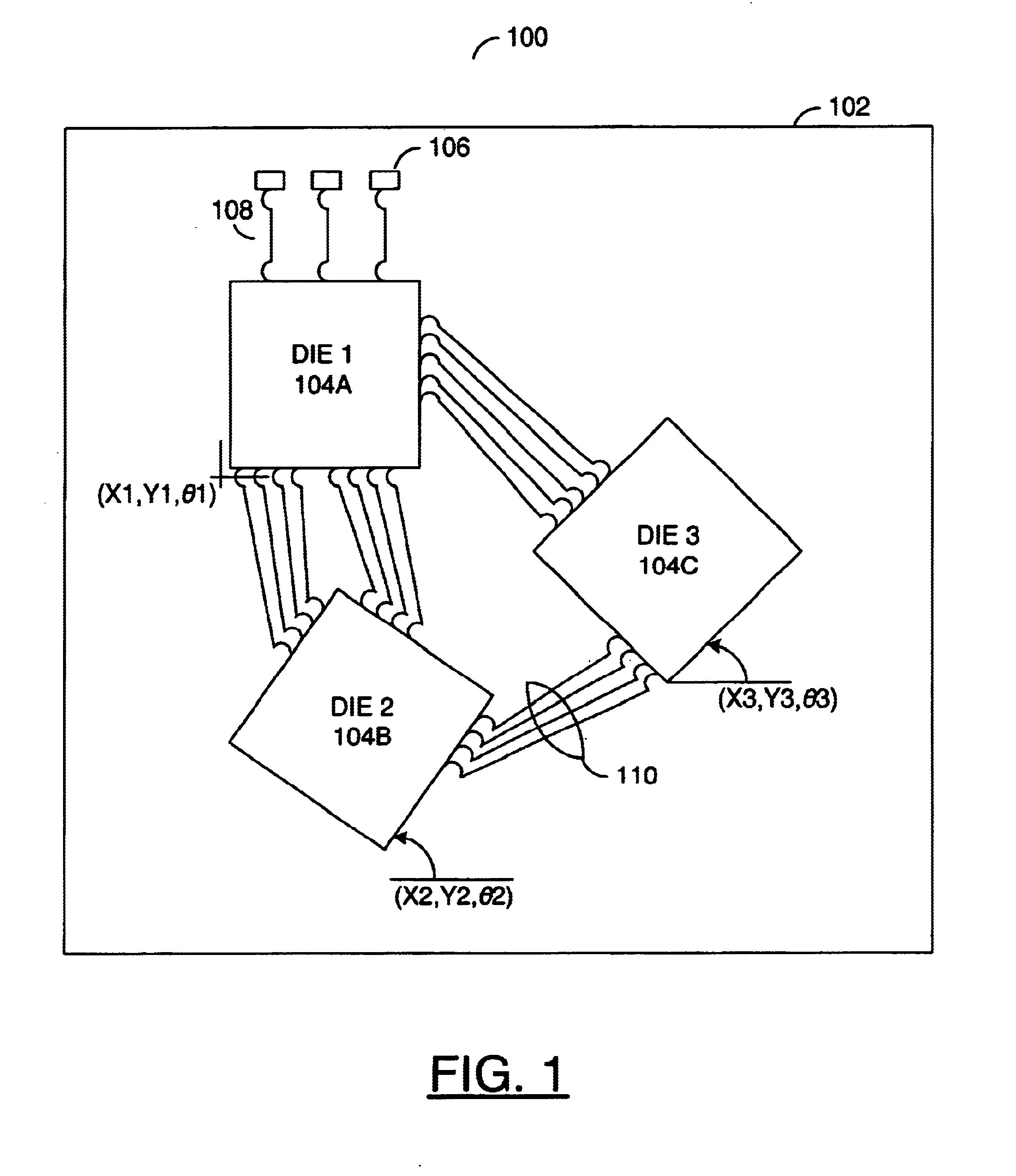
With the Cartesian approach, the routing becomes unnecessarily long due to large distances between pads on different dies that are not on edges facing each other.
The non-facing pad situation complicates and lengthens routes and causes increased signal propagation delays.
A large number of long traces on the substrate commonly reduces available space for routing.
The reduced available space potentially causes difficulty in substrate designs where a number of traces are required, such as feature-rich devices.
In some cases, a larger package size is required to accommodate the inefficient routing, thus increasing signal delays.

Method used


Image

  • Method for determining die placement based on global routing architecture
  • Method for determining die placement based on global routing architecture
  • Method for determining die placement based on global routing architecture

Examples


Embodiment Construction

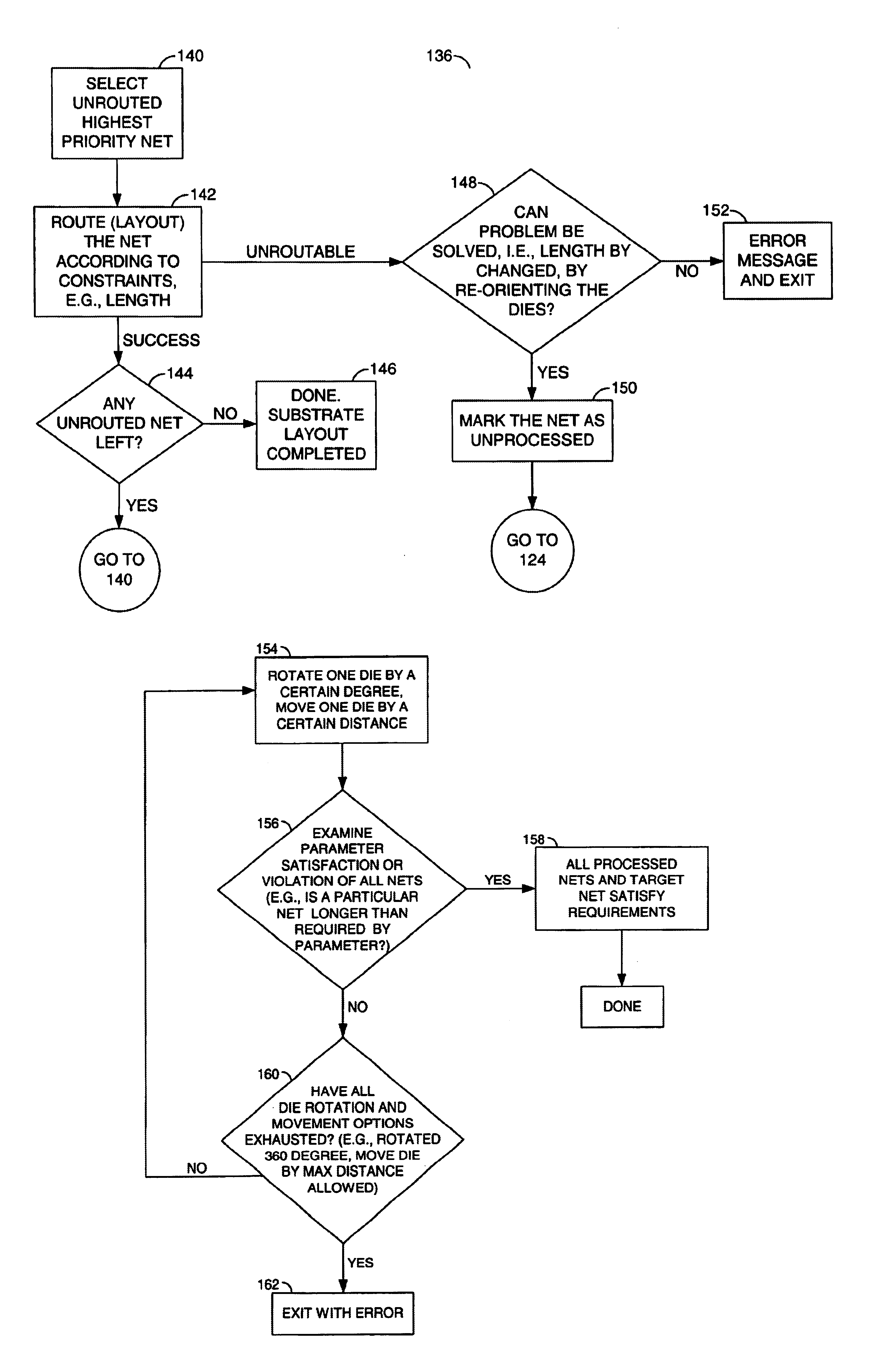
The invention generally defines a die placement process for determining optimal die placement and die angles in a multi-chip package where the dies may be relatively rotated from the perspective of traditional Cartesian approach in which the dies are placed in a rigid imaginary x-y coordinate system. The process may orient some or all of the dies non-parallel and non-perpendicular to the x-y axes. The process may also result in die angles of 0, 90, 180, 270, and 360 degrees relative to the x-y coordinate system.

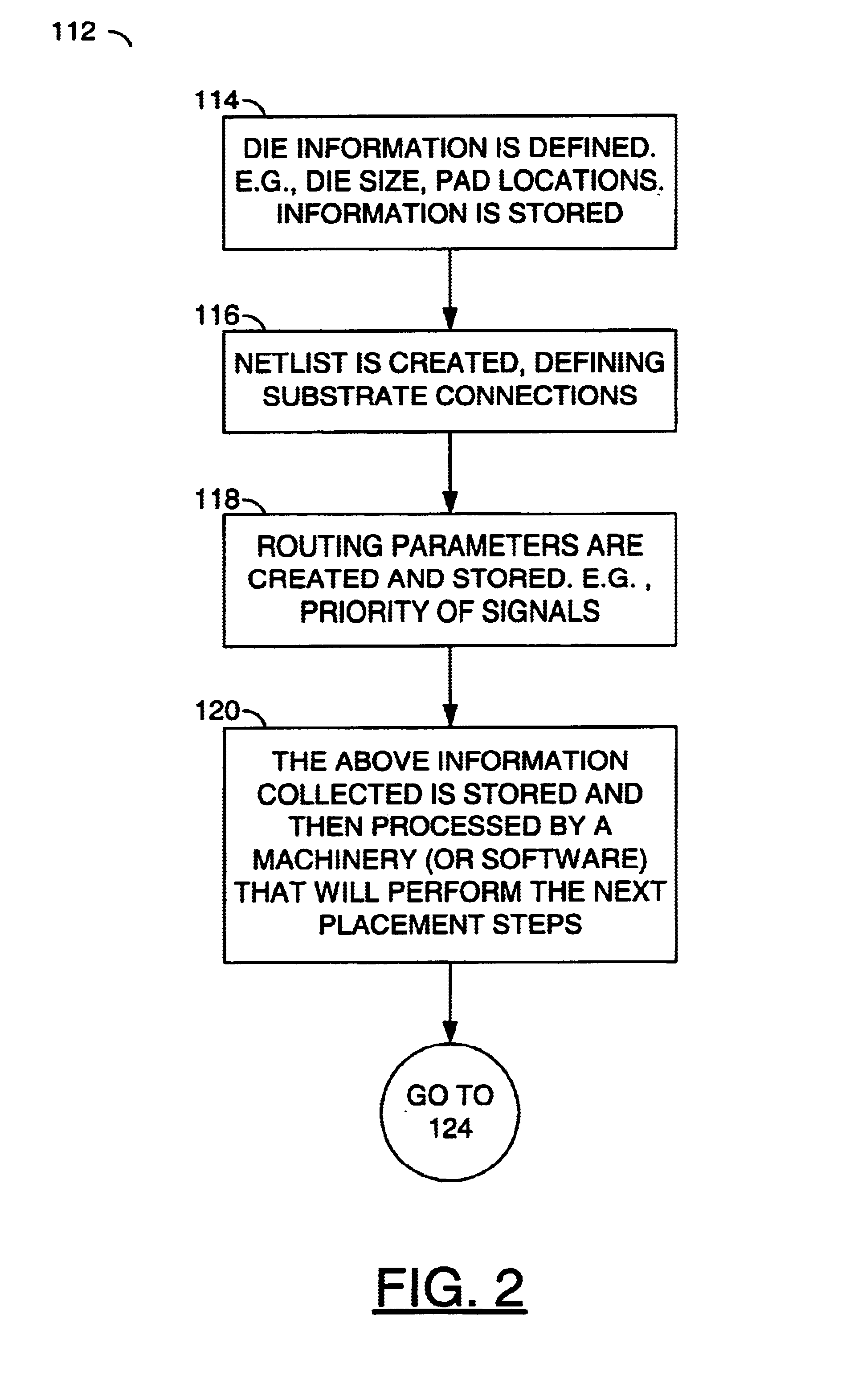
The process for determining relative die placement and die angles on the substrate may minimize routing complexity, increase routing space, and reduce trace lengths. The process may achieve the above by taking into account various routing requirements, rules and parameters for substrate connections and then finding the appropriate placement and angles. The dies in the package are generally existing dies with information at least sufficient for the die placement process define...


PUM


Abstract

A method for interconnecting a plurality of dies. The method generally includes receiving a plurality of interconnect requirements for the dies. The interconnect requirements may include a priority for each of a plurality of nets. A position and an angle for one of the dies relative to a substrate may be calculated in response to the interconnect requirements. A plurality of nets may then be routed among the dies and a plurality of substrate pads defining external connections for the substrate. The dies may be mounted to the substrate after routing has been finalized.

Description

FIELD OF THE INVENTIONThe present invention relates to a method and / or architecture for automatic trace routing and, more particularly, to a method and / or architecture for determining die placement and die orientation with respect to a substrate to achieve interconnection requirements.BACKGROUND OF THE INVENTIONConventional multi-die semiconductor packages are organized internally about Cartesian coordinates. One consequence of the Cartesian organization is that some traces on the substrate follow long and complex routes. With the Cartesian approach, the routing becomes unnecessarily long due to large distances between pads on different dies that are not on edges facing each other. The non-facing pad situation complicates and lengthens routes and causes increased signal propagation delays.A large number of long traces on the substrate commonly reduces available space for routing. The reduced available space potentially causes difficulty in substrate designs where a number of traces ...

Claims


Application Information

Patent Timeline
IPC IPC(8): G06F17/50
CPCG06F17/5077G06F17/5072G06F30/392G06F30/394G06F30/3947
Inventor WRIGHT, ANDREW J.LIE, JAMES H.
Owner DECA TECH INC
Learn More