Automatic equalization circuit and receiver circuit using the same

a receiver circuit and equalization circuit technology, applied in the field of equalization circuits, can solve the problems of inability to notify, take a long time, and the transmission apparatus side has no means of knowing the completion of setting equalization characteristics, so as to reduce the size of the program, shorten the process time, and reduce the circuit scale

Inactive Publication Date: 2005-04-12
KOKUSA ELECTRIC CO LTD
View PDF16 Cites 15 Cited by
  • Summary
  • Abstract
  • Description
  • Claims
  • Application Information

AI Technical Summary

Benefits of technology

It is an object of the present invention to provide an automatic equalization circuit and a reception circuit (demodulation circuit) using the automatic equalization circuit, capable of shortening the process time and reducing the size of programs if tap updating is performed by using software, and reducing the circuit scale if it is performed by using hardware, while the equalization convergence performance is retained.
Since a two-level training signal is symmetrical relative to a phase difference of π, a reference signal of only the in-phase component or quadrature component is generated when the training signal is received, and the tap coefficient updating is performed by using the reference signal. When the tap coefficient updating by using the training signal is completed, the phase of each tap coefficient is rotated. In this manner, the complex number or complex number calculation can be simplified, and the loads of the tap coefficient updating and filter calculations of the automatic equalization circuit can be reduced. When the tap coefficient updating is completed, the phase of each tap coefficient value is rotated to have the same phase as the original training signal. Received data signals can therefore be reproduced in a manner similar to a conventional manner.

Problems solved by technology

However, the transmission apparatus side has no means for knowing the completion of setting the equalization characteristics on the reception apparatus side.
Even if the equalization condition could be recovered by some other means, it takes a very long time.
However, if data transmission is carried out unidirectionally, this notification is impossible.
When the divergence of the equalizer occurs, the reception apparatus side cannot reproduce the data signal correctly, resulting in bit errors.
Therefore, according to this conventional automatic equalization technique, even if the divergence condition of the equalizer occurs, bit errors of data signals are generated only during the period from the occurrence of the divergence to the completion of setting the equalization characteristics by using the next training signal.
However, with the above-described automatic equalization technique, the calculation amount becomes very large because the above-described equations are calculated for each tap and the input signal is represented by a complex number and has both the in-phase and quadrature amplitude components.
If the tap coefficient updating is performed by using software, the process time becomes very long and the program itself becomes large, and if the tap coefficient updating is performed by using hardware, the circuit scale becomes very large.

Method used


Image

  • Automatic equalization circuit and receiver circuit using the same
  • Automatic equalization circuit and receiver circuit using the same
  • Automatic equalization circuit and receiver circuit using the same

Examples


Embodiment Construction

Embodiments of the invention will be described with reference to the accompanying drawings. In the drawings, like elements are represented by identical reference numerals and the duplicated description thereof is omitted.

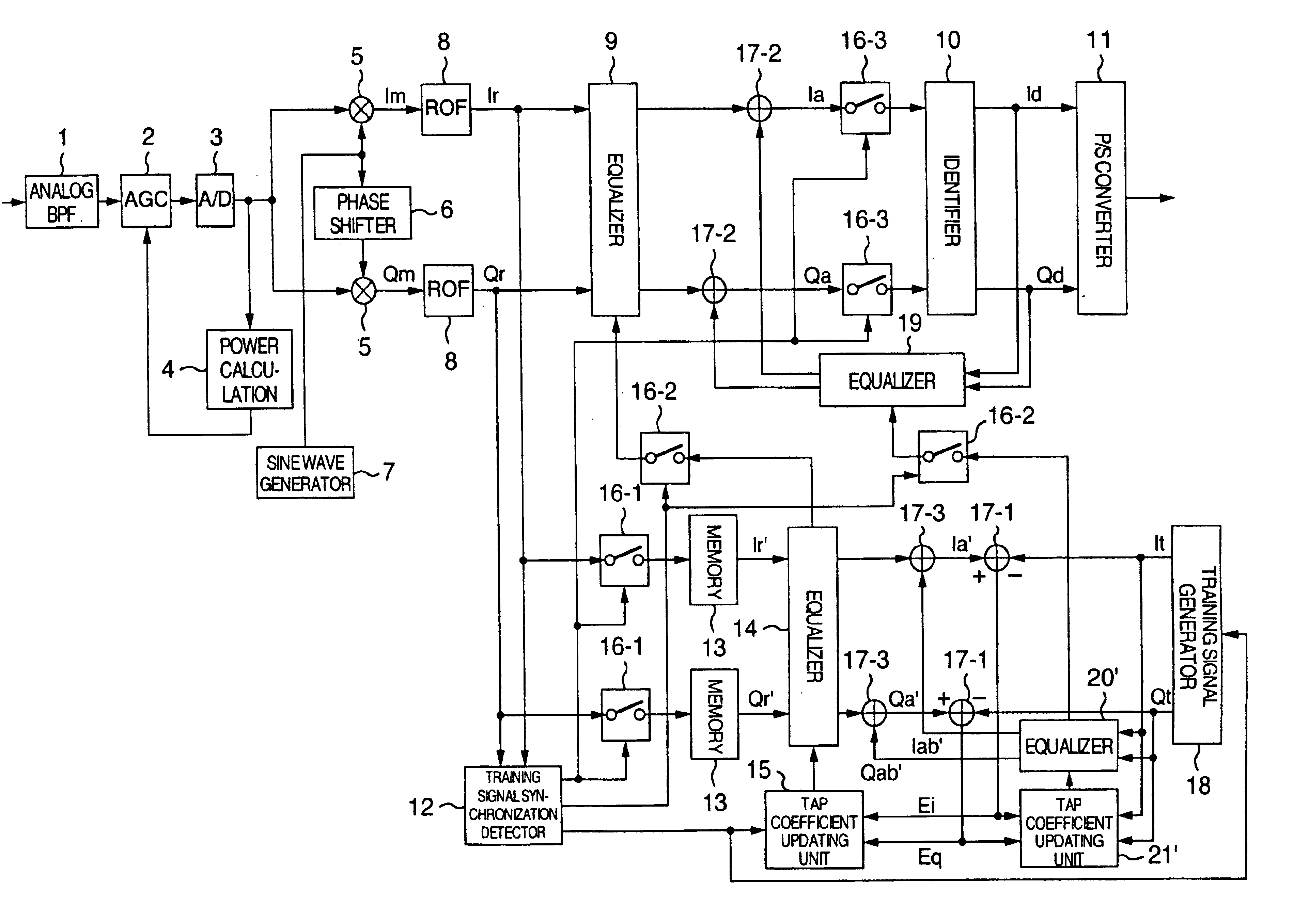
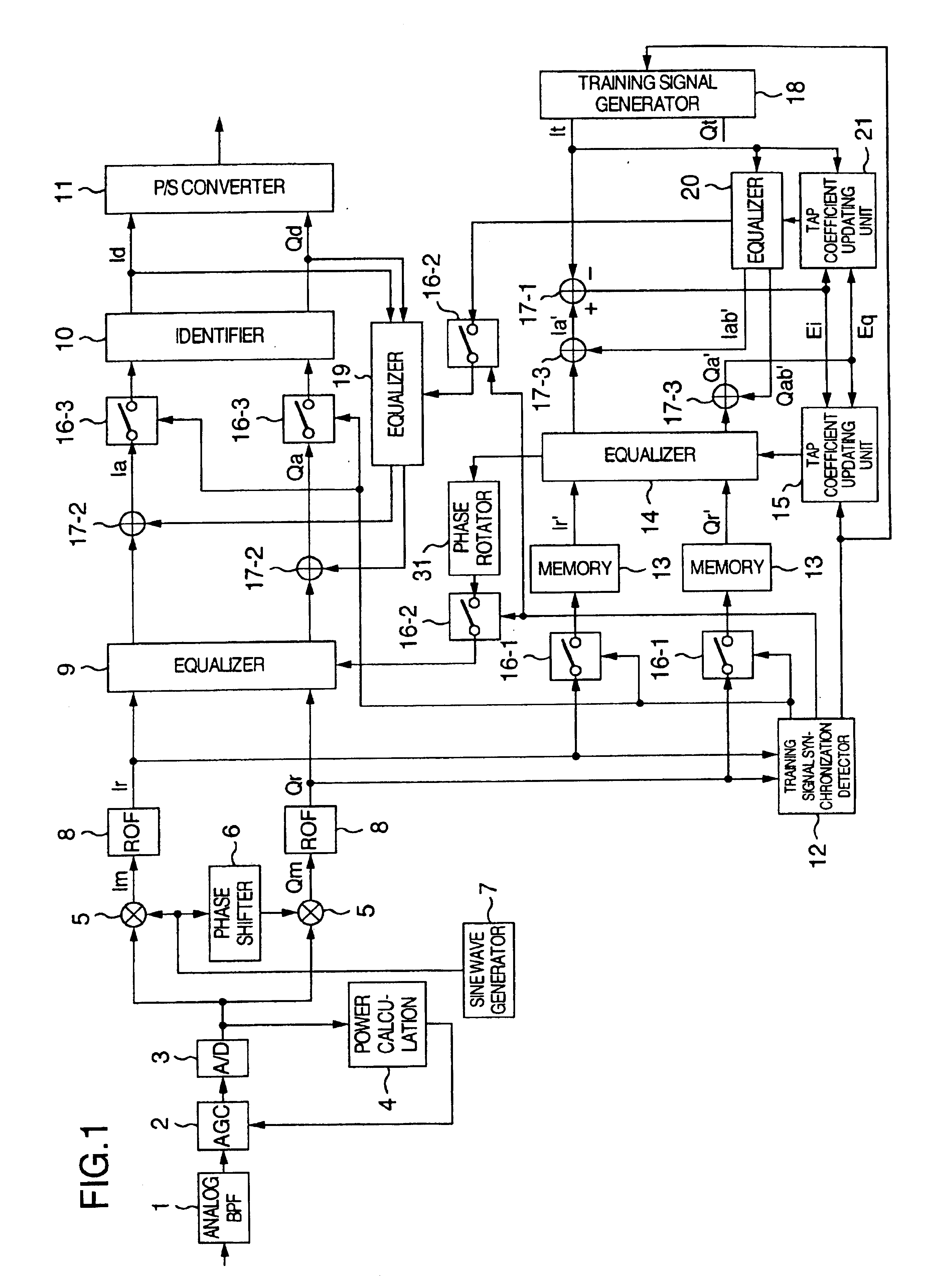
With reference to FIG. 12, a demodulation circuit (receiver circuit) embodying the invention will be described, which circuit includes an automatic equalization circuit including decision feedback equalizers. The decision feedback equalizer shown in FIG. 12 has been proposed by the inventors of the present invention and is not prior art. Obviously, the invention is not limited only thereto, but is also applicable to other types of automatic equalization circuits.

In FIG. 12, blocks 9, 12, 13, 14, 15, 16-1, 16-2, 16-3, 17-1, 17-2, 17-3, 18, 19, 20′ and 21′ constitute the automatic equalization circuit.

An analog BPF 1, an AGC circuit 2, an A / D converter 3, a reception power calculating unit 4, multipliers 5, a phase shifter 6, a sine wave oscillator 7, and roll-off fil...


PUM


Abstract

A demodulation circuit for demodulating a multilevel digital modulation signal. Only an in-phase or quadrature component of the training signal generated in the demodulation circuit is used for equalization convergence. Tap coefficients of an equalizing training equalizer are updated by supplying either the in-phase or quadrature component so that the calculation amount can be reduced. When the equalization convergence is established, the obtained tap coefficients are rotated in phase and set to a data reproduction equalizer.

Description

BACKGROUND OF THE INVENTIONThe present invention relates to an equalization circuit to be used in a demodulation circuit for demodulating a multilevel digital modulation signal, and more particularly to an automatic equalization circuit of the type that equalization characteristics, i.e., frequency characteristics, are automatically set by using a training signal, and to a receiver circuit (demodulation circuit) using such an automatic equalization circuit.It is desired in every and each transmission system including a multilevel digital transmission system that waveform distortions, echoes and the like be as small as possible. It is known that an automatic equalizer is used in a demodulation circuit (receiver circuit) for demodulating a modulation signal of a multilevel digital modulation type. Examples of using an automatic equalizer are disclosed, for example, in Shahid U. H. Qureshi, “Adaptive Equalization”, Proceedings of the IEEE, Vol. 73, No. 9, September 1985, pages 1349 and...

Claims


Application Information

Patent Timeline
Patent Type & Authority Patents(United States)
IPC IPC(8): H04L25/03
CPCH04L25/03133H04L2025/0377H04L2025/03477
Inventor KOKURYO, YOSHIROTSUKAMOTO, NOBUOHAMAZUMI, HIROYUKI
Owner KOKUSA ELECTRIC CO LTD
Why Eureka
Try Eureka