
Frequency modulation corrector keeping a good oscillating signal quality and suppressing dependability of a modulation degree

a frequency modulation and corrector technology, applied in the direction of angle modulation details, oscillating generators, pulse automatic control, etc., can solve the problems of increasing the modulation degree to frequency, complicated structure of the resonant circuit, and bulky resonant circuit, so as to reduce the capacitance of the second capacitor element, suppress the carrier frequency dependency of the modulation degree, and reduce the modulation degree

Inactive Publication Date: 2005-04-12
LAPIS SEMICON CO LTD
View PDF2 Cites 3 Cited by
  • Summary
  • Abstract
  • Description
  • Claims
  • Application Information

AI Technical Summary

Benefits of technology

It is an object of the present invention to overcome the defects of the conventional technique and to provide a frequency modulation corrector in which it is possible to suppress the carrier frequency dependency of the modulation degree to frequency with the noise characteristics of the oscillator kept at an optimum level even though the modulation degree to frequency remains uncorrected.
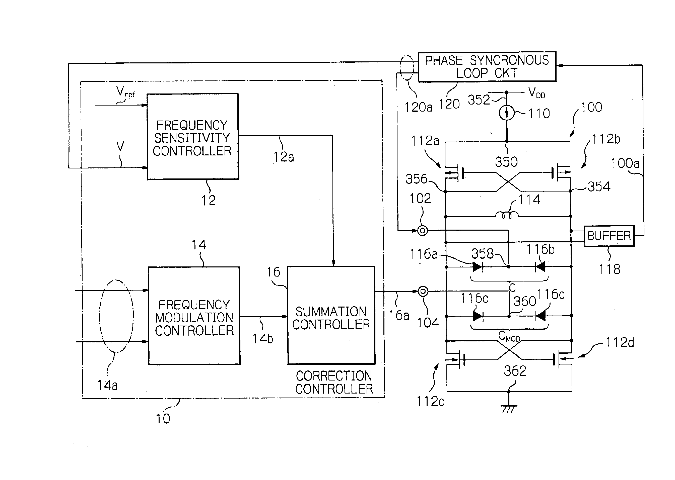
The frequency modulation corrector of the present invention is thus arranged outwardly of the voltage-controlled oscillator. In order that the oscillation of the selected frequency and the frequency modulation will be carried out independently of each other, a DC signal is generated in the frequency setting circuit, and the modulation adjusting signal, not dependent on the DC signal, is generated in the modulation degree setting circuit. The DC signal and the modulation adjusting signal are summed in the signal summation circuit which then sends out a second control voltage signal to a voltage-controlled oscillator to be controlled. The voltage-controlled oscillator is responsive to the increasing frequency to lower the capacitance of the second capacitor element to decrease the modulation degree to maintain the modulation degree to frequency at a substantially constant value. In this manner, noise characteristics of the oscillation circuit may be maintained at an optimum level, even in the absence of the correction in the modulation degree to frequency, thereby suppressing the carrier frequency dependency of the modulation degree to frequency as well as providing tolerance for noise increase.

Problems solved by technology

This circuit structure, however, suffers from a deficiency that the modulation degree to frequency is increased with the increasing carrier frequency.
Meanwhile, since the aforementioned Japanese Laid-Open patent Publication No. 2001-196860 uses, in addition to the first and second variable capacity elements used in the resonant circuit, the third variable capacitor element to compensate for the aforementioned effect, resulting in the resonant circuit being complicated in structure and bulky due to the additional constituent element.
If nevertheless the designing is changed to introduce the third variable capacitor element and the resistor and to meet the specifications for the noise characteristics in the oscillator or resonant circuit, the space occupied or the power consumption would be increased, so that the competitive power of the product is lost.

Method used


Image

  • Frequency modulation corrector keeping a good oscillating signal quality and suppressing dependability of a modulation degree
  • Frequency modulation corrector keeping a good oscillating signal quality and suppressing dependability of a modulation degree
  • Frequency modulation corrector keeping a good oscillating signal quality and suppressing dependability of a modulation degree

Examples


first modification

(First Modification)

With reference to FIG. 5, the frequency sensitivity controller 12 includes an operational amplifier 12c, resistors 12d and 12e, a transfer gate 12f and a frequency synthesizer 12g, interconnected as shown. The parts or components common to those of the previous embodiment are denoted with the same reference numerals and hence the description on the corresponding operation is omitted for simplicity. The resistor 12e, grounded, includes resistors 120e and 122e, which are connected in series with each other to establish the same resistance value as the resistor 12e of the embodiment shown in FIG. 3.

The transfer gate 12f is a switching element responsive to the control signal 12h supplied thereto for switching itself between the conductive and non-conductive states. The transfer gate 12f is connected in parallel with the resistor 120e. The transfer gate 12f operates responsive to the control signal 12h supplied from the frequency synthesizer 12g to be conductive in r...

second modification

(Second Modification)

Referring to FIG. 7, the frequency sensitivity controller 12 includes an operational amplifier 12c, resistors 12d and 12e, transfer gates 12f, 12i and 12j, and a frequency synthesizer 12g. It is noted that the same reference numerals as those used in the previous embodiment or modification are used to designate the corresponding parts or components and the detailed description therefor is omitted for simplicity.

In the present embodiment, shown in FIG. 7, the resistor 12e is comprised of a parallel connection of a series connection of a resistor 200 and the transfer gate 12i and another series connection of a resistor 202 and the transfer gate 12j. The transfer gate 12f is connected in parallel across the resistors 12d and 122e, as in the previous embodiment.

The frequency synthesizer 12g is of the same configuration as in the first modification, and has the function of generating and outputting control signals 12h and 12k, adapted for opening and closing the tran...

third modification

(Third Modification)

The third modification will now be described. In the present embodiment, the frequency sensitivity controller 12, shown in FIG. 3, is applied so as to change the amplification factor of the frequency modulation controller 14 as shown in FIG. 9.

The frequency modulation controller 14 is basically similar to the configuration shown in FIG. 3 except that resistors 148a and 148b, transfer gates 148e and 148f, and a frequency synthesizer 148g have been added in the frequency modulation controller 14 shown in FIG. 9.

The resistor 148a includes a series connection of resistors 1480 and 1482, while the resistor 148b includes a series connection of resistors 1484 and 1486. The transfer gates 148e and 148f are connected in parallel with the resistors 1482 and 1484, respectively. The nodes 364 of the parallel connection of the transfer gates 148e and 148f are connected in common.

The frequency synthesizer 148g includes a programmable counter 1488 which forms a component of a f...


PUM


Abstract

A correction circuit for a voltage-controlled oscillator (VCO) is arranged outwardly of the voltage-controlled oscillator. The oscillation of the selected frequency and the frequency modulation are carried out independently of each other. The correction circuit includes a frequency selection controller generating a frequency selection signal of the DC potential, and a frequency modulation controller generating a modulation adjusting signal responsive to the input of a modulating signal. When a frequency modulation control signal, including the DC potential of the frequency selection signal and the modulation adjusting signal, is supplied to the voltage-controlled oscillator, the capacitance is lowered even if the frequency is increased, thus allowing the modulation degree to frequency to be decreased to a substantially constant level.

Description

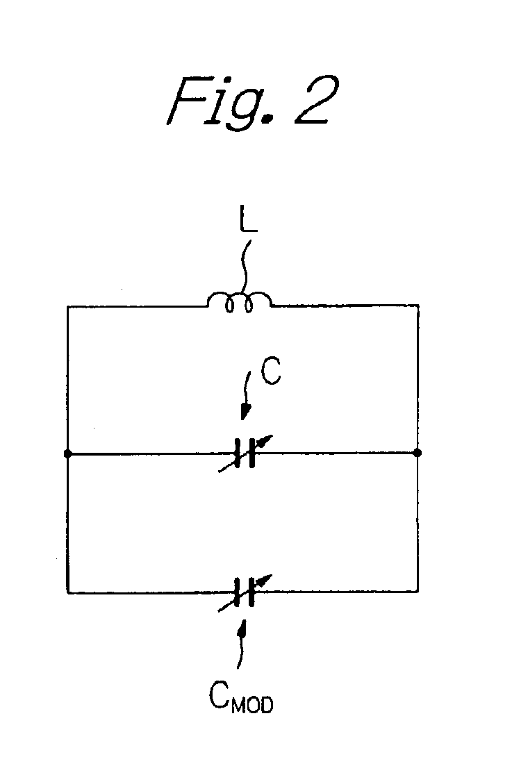
BACKGROUND OF THE INVENTION1. Field of the InventionThe present invention relates to a frequency modulation corrector and, more particularly, to a circuit for correcting the modulation degree to frequency in for example a voltage-controlled oscillator (VCO).2. Description of the Background ArtIn general, a voltage-controlled oscillator, used in a wireless device of a conventional direct frequency modulation system, may be represented by an equivalent circuit including, as a resonant circuit, a fixed inductor, a first variable capacitor element for selecting the carrier frequency and a second variable capacitor element responsible for frequency modulation. The first and second variable capacitor elements are connected in parallel to each other. The voltage-controlled oscillator also includes an amplifier circuit for use in oscillating the resonant circuit. The voltage-controlled oscillator, formed by this resonant circuit, selects the carrier frequency by the direct current (DC) pote...

Claims


Application Information

Patent Timeline
Patent Type & Authority Patents(United States)
IPC IPC(8): H03C3/22H03C3/00H03L7/099H03L7/08H03B5/08H03B5/12H03C3/06
CPCH03C3/225H03L7/099H03B5/1221H03B5/1225H03B5/1215H03B5/1243H03B5/1209H03B5/1228H03L2207/06
Inventor FUJITA, KEN
Owner LAPIS SEMICON CO LTD
Learn More