
Microfluidic system including a bubble valve for regulating fluid flow through a microchannel

a microfluidic system and microchannel technology, applied in the direction of diaphragms, particle and sedimentation analysis, biological material analysis, etc., can solve the problems of requiring power to operate the valve, and affecting the flow rate of fluid through the microchannel

Inactive Publication Date: 2005-04-12
CYTONOMEST
View PDF17 Cites 144 Cited by
  • Summary
  • Abstract
  • Description
  • Claims
  • Application Information

AI Technical Summary

Benefits of technology

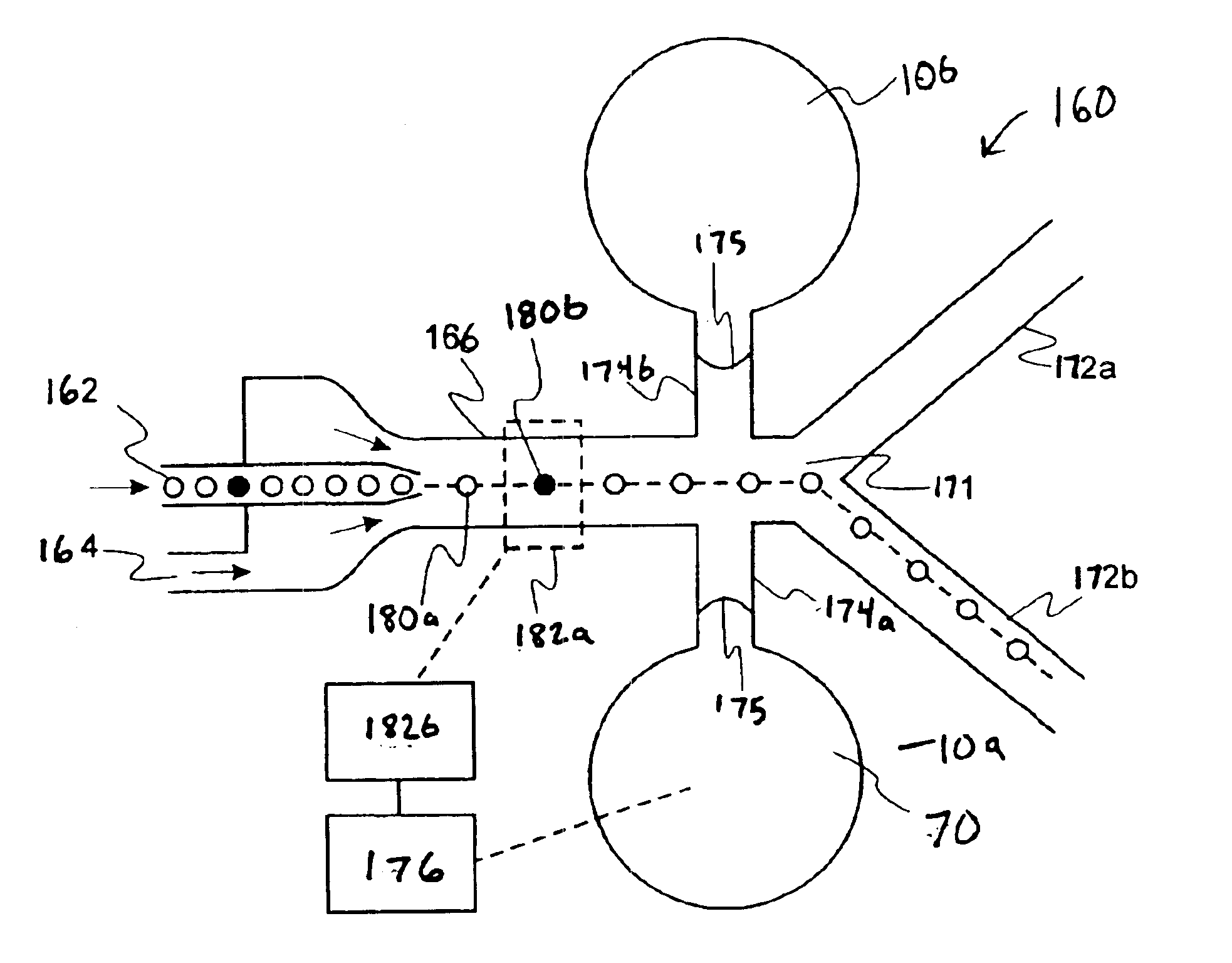
The present invention provides a bubble valve for controlling, regulating or varying fluid flow through a microfluidic system. The bubble valve regulates fluid flow through a channel using an externally operated mechanical or pneumatic actuator. The actuator causes a deflection of a fluid meniscus into the interior of the channel to regulate liquid flow. The actuator may mechanically force a gas bubble into a fluid carrying microchannel to inhibit liquid flow or to cause liquid flow by applying a sufficiently high pressure to the meniscus. The bubble valve effectively controls the flow of liquids in microfluidic systems, without heating the fluid and without complex on-chip circuitry.
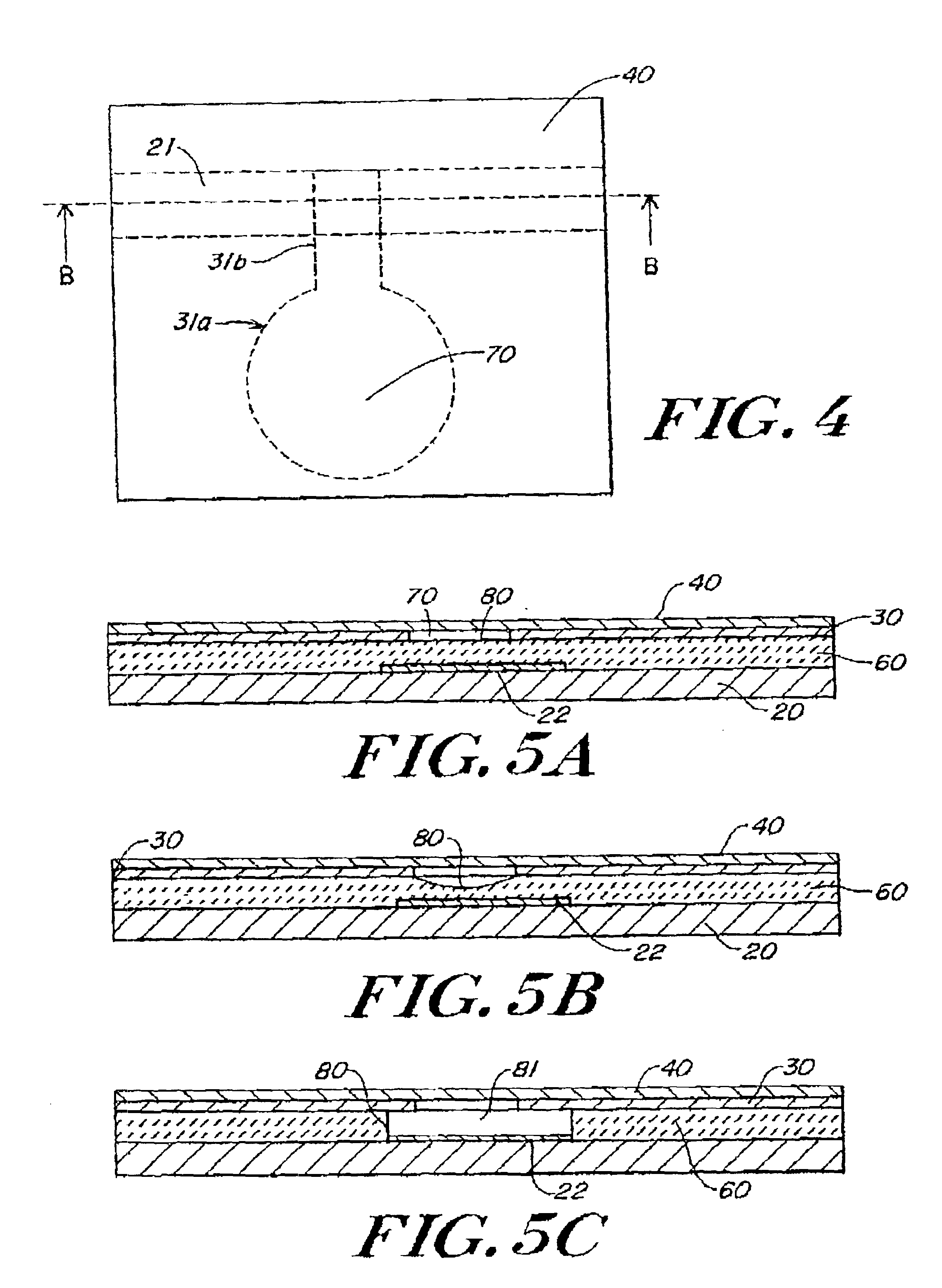
According to one embodiment, the microchannel includes a hydrophobic patch spanning the width of the microchannel at the location where the gas bubble is introduced to enhanced on-off switching of the bubble valve. The hydrophobic patch anchors the bubble in a particular location in the microchannel. If the introduced gas bubble covers the whole area of the patch, the bubble is effectively retained by capillary forces and blocks any liquid flow up to a certain pressure difference, depending on the level of hydrophobicity of the patch.
Alternatively or in combination with a hydrophobic patch, the microchannel can be locally shaped into a cavity for receiving and anchoring the gas bubble. By providing an appropriate cavity, the bubble can be kept in place during operation, reducing the risk that the gas bubble is carried away with the liquid.

Problems solved by technology

Another example of the efficiency of microfluidic systems is the mixing of dissolved species in a liquid, a process that is also diffusion limited.
The described system presents a number of disadvantages, namely, the required power to operate the valve and the inherent requirement that liquid in the channel be heated upon passing the valve.
Even small increases in liquid temperature, by only a couple of degrees, can have disastrous effects on the highly heat sensitive biochemical substances present in the liquids to be controlled in many microfluidic systems.
In addition, the required on-chip electric circuitry for the heater increases the complexity of the described valve and consequently results in unacceptably high costs, particularly if the fluidic system employing the bubble valve only used for a single application.

Method used


Image

  • Microfluidic system including a bubble valve for regulating fluid flow through a microchannel
  • Microfluidic system including a bubble valve for regulating fluid flow through a microchannel
  • Microfluidic system including a bubble valve for regulating fluid flow through a microchannel

Examples


Embodiment Construction

The present invention provides an improved bubble valve for controlling fluid flow through a microchannel in a microfluidic system. The invention further provides a method of forming the bubble valve. The bubble valve of the present invention can be applied in numerous microfluidic systems for controlling and switching fluid flows. Examples of suitable applications include, but are not limited to: flow cytometry, column switching, 2-D separations, cell or particle sorting applications on a chip, regulating pressurized fluid flows including on-off switching, regulating electrokinetic fluid flows and electrokinetically induced processes including on-off switching and electrokinetic sample injection and channel to channel switching.

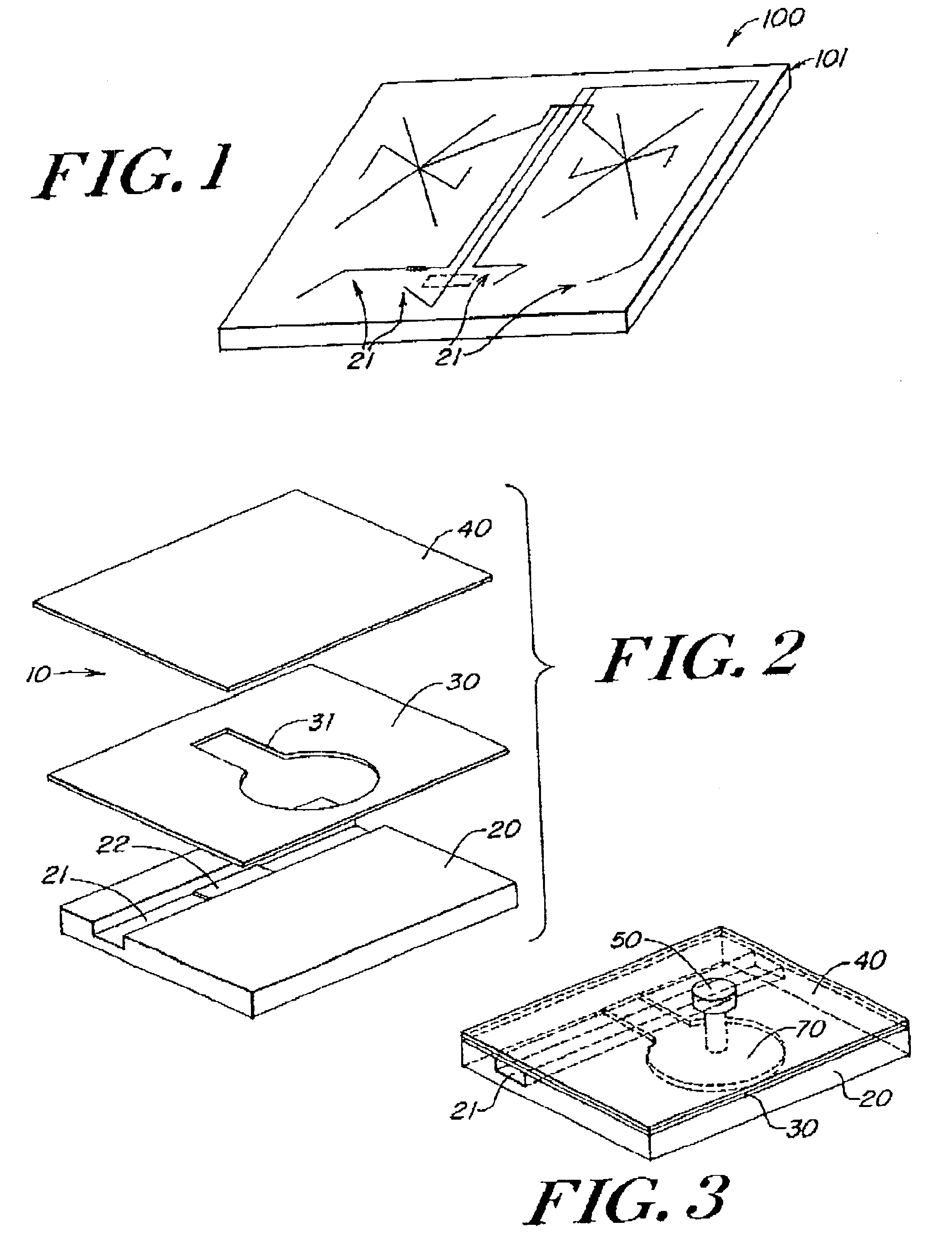
FIG. 1 illustrates a microfluidic system suitable for implementing the illustrative embodiment of the present invention. The illustrative microfluidic system 100 comprises a substrate 101 having one or more microchannels 21 disposed therein. The microchannel...


PUM

PropertyMeasurementUnit
Pressureaaaaaaaaaa
Flow rateaaaaaaaaaa
Flexibilityaaaaaaaaaa

Abstract

A microfluidic system includes a bubble valve for regulating fluid flow through a microchannel. The bubble valve includes a fluid meniscus interfacing the microchannel interior and an actuator for deflecting the membrane into the microchannel interior to regulate fluid flow. The actuator generates a gas bubble in a liquid in the microchannel when a sufficient pressure is generated on the membrane.

Description

FIELD OF THE INVENTIONThe present invention relates to microscale fluid handling devices and systems. More particularly, the present invention relates to a method and system for controlling liquid flow in a microchannel by the introduction of a gas bubble to a microfluidic system.BACKGROUND OF THE INVENTIONIn the chemical, biomedical, bioscience and pharmaceutical industries, it has become increasingly desirable to perform large numbers of chemical operations, such as reactions, separations and subsequent detection steps, in a highly parallel fashion. The high throughput synthesis, screening and analysis of (bio)chemical compounds, enables the economic discovery of new drugs and drug candidates, and the implementation of sophisticated medical diagnostic equipment. Of key importance for the improvement of the chemical operations required in these applications are an increased speed, enhanced reproducibility, decreased consumption of expensive samples and reagents, and the reduction o...

Claims


Application Information

Patent Timeline
IPC IPC(8): B07C5/34F15C5/00B01L3/00G01N15/14F16K99/00
CPCB01L3/502738B07C5/34F16K99/0001F16K99/0017F16K99/0019F16K99/0034F16K99/0036F16K99/004F16K99/0046F16K99/0048B01L3/502761Y10T29/49405B01L3/502776B01L2200/0636B01L2200/0647B01L2300/0816B01L2300/0864B01L2300/089B01L2400/0415B01L2400/06B01L2400/0688B01L2400/082F16K2099/0074F16K2099/008F16K2099/0084G01N2015/149Y10T436/143333Y10T137/2207Y10T137/0497Y10T137/2196Y10T137/2191Y10T137/2082Y10T137/2076Y10T137/0396Y10T137/0318Y10T137/2224Y10T137/2202Y10T137/2213Y10T436/25375G01N15/149
Inventor GILBERT, JOHN RICHARDBOHM, SEBASTIANDESHPANDE, MANISH
Owner CYTONOMEST
Learn More