Manufacturing method of a thin film magnetic head

a manufacturing method and technology of a applied in the field of thin film magnetic recording/reproducing head, can solve the problems of inability to accurately form the method disclosed, and the large thickness of the upper magnetic core, etc., to achieve high speed

Inactive Publication Date: 2005-04-12
HITACHI GLOBAL STORAGE TECH JAPAN LTD
View PDF13 Cites 6 Cited by
  • Summary
  • Abstract
  • Description
  • Claims
  • Application Information

AI Technical Summary

Benefits of technology

An object of the present invention is to provide a magnetic disk apparatus exhibiting an areal recording density of 5 Gbit / in2 or more by using a recording / reproduction separation type thin film magnetic head having a narrow track width of 1 μm or less or capable of keeping up with data transfer at a high speed.

Problems solved by technology

The upper magnetic core having such a large thickness, however, cannot be accurately formed by the process using dry etching such as ion milling.
The resist having a thickness of 1 μm or less, however, is too thin to be used for a resist frame, and therefore, such a resist cannot be used for formation of a magnetic core.
The method disclosed in this document, however, is poor in dimensional accuracy because etching is performed using the resist pattern as a mask.
Another problem of this method is that a magnetic pole end of an upper magnetic pole layer is emerged at the face, opposed to a medium, of a magnetic core, and accordingly a magnetic flux leaked from the magnetic pole end of the upper magnetic pole layer may write or erase signals, to thereby enlarge an effective track width.
To solve the above problem, it may be considered to form the upper magnetic pole layer by frame plating in such a manner as to prevent the magnetic pole end of the upper magnetic pole layer from being emerged at the face, opposed to a medium, of the magnetic core; however, in this case, there arises a problem that it is difficult to accurately form a frame for plating because of halation from a coil insulating film as shown in FIG.
Hei 6-20227, however, since a end portion of the magnetic core is formed after formation of a stepped portion of the coil insulating film, the thickness of the resist becomes large at the stepped portion of the coil insulating film, and thereby it is difficult to form the resist pattern of about 1.5 μm.
Also when the track width is made as narrow as about 1.5 μm, magnetic saturation occurs at the narrow portion, to cause a problem that it is difficult for a magnetic field to be emerged to the face, opposed to a medium, of the magnetic core.
Eventually, it is difficult to select a material capable of satisfying these requirements.

Method used


Image

  • Manufacturing method of a thin film magnetic head
  • Manufacturing method of a thin film magnetic head
  • Manufacturing method of a thin film magnetic head

Examples


Embodiment Construction

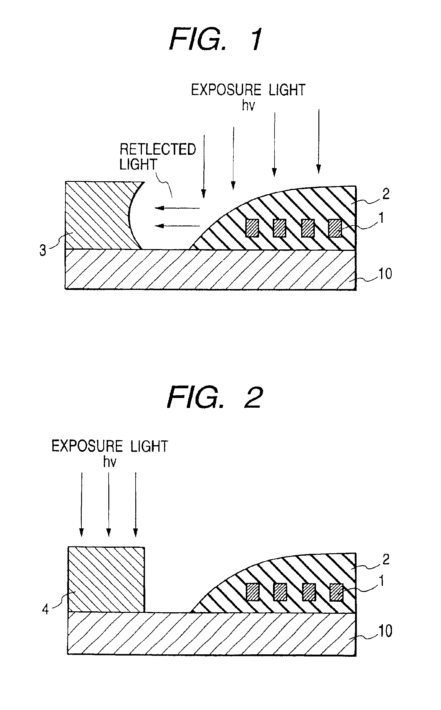
To increase the recording density of a magnetic disk apparatus, as described above, it is required to attain a narrow track width of a magnetic head, and to satisfy such a requirement, it is necessary to form a fine resist pattern. To form a fine resist pattern, the wavelength of light for exposure of the resist has been shortened. For example, the exposure light has been changed from g-line (wavelength: 436 nm) to i-line (wavelength: 365 nm) of the mercury lamp, and further changed to KrF excimer laser (wavelength: 248 nm). As described above, to ensure a desired depth of focus with a specific resolution, it is necessary to shorten the wavelength of light for exposure and to reduce the numerical aperture (NA); however, it is difficult to form a pattern of 0.5 μm required for formation of an upper magnetic core having a narrow track width by using a resist having a thickness of 3 μm or more. To cope with such an inconvenience, it may be considered to produce the upper magnetic core ...


PUM

PropertyMeasurementUnit
distanceaaaaaaaaaa
widthaaaaaaaaaa
widthaaaaaaaaaa

Abstract

A magnetic disk apparatus includes a magnetic reproducing head portion, and a magnetic recording head including a lower magnetic core and an upper magnetic core having a end portion and a rear portion. The rear portion is formed using a negative resist or an electron beam resist to form a frame for plating above the end portion of the upper magnetic core head.

Description

BACKGROUND OF THE INVENTION1. Field of the InventionThe present invention relates to a thin film magnetic recording / reproducing head used for a magnetic disk apparatus, and a magnetic disk apparatus or recording / reproducing apparatus including the same.2. Description of the Related ArtIn a magnetic disk apparatus, data are written or read on or from a recording medium or magnetic disk by a magnetic head. To increase a recording capacity per unit area of a magnetic disk, an areal recording density is required to be enhanced. The areal recording density can be enhanced by increasing a track density and a linear recording density. To increase the track density of the above two factors for enhancing the areal recording density, the track width of the magnetic head is required to be made fine and precise. As the track width becomes narrower, a reproducing output becomes smaller, and therefore, to attain a narrower track width, a reproducing head is required to be changed from a MR (Magne...

Claims


Application Information

Patent Timeline
Patent Type & Authority Patents(United States)
IPC IPC(8): G11B5/31G11B5/012G11B5/39
CPCG11B5/3116G11B5/3163G11B5/012Y10T29/49044Y10T29/49043Y10T29/49052Y10T29/49041Y10T29/49046Y10T29/49032Y10T29/49048
Inventor OKADA, TOMOHIROOKAI, TETSUYASASAKI, SHINOBUIWAKURA, TADAYUKIKOYAMA, NAOKISAITO, HARUNOBUMORIJIRI, MAKOTO
Owner HITACHI GLOBAL STORAGE TECH JAPAN LTD
Why Eureka
Try Eureka