Eureka AIR delivers breakthrough ideas for toughest innovation challenges, trusted by R&D personnel around the world.

Disk array system

a technology of disk array system and hard disk unit, which is applied in the direction of memory address/allocation/relocation, redundant hardware error correction, instruments, etc., can solve the problems of disk array system, disk array system, and inability to take data coordination, so as to prevent the trouble caused by moving the disk array system and improve the working efficiency.

Inactive Publication Date: 2005-04-05
HITACHI LTD
View PDF12 Cites 9 Cited by
  • Summary
  • Abstract
  • Description
  • Claims
  • Application Information

AI Technical Summary

Benefits of technology

The present invention relates to a method for controlling hard disk units in a disk array system. The technical effects of the invention include the ability to manage data coordination even when multiple hard disk units are removed or inserted, the ability to protect data from damage due to erroneous positioning of hard disk units during transportation, and the ability to easily restore the arrangement of hard disk units when they are removed and re- inserted. These features improve the reliability and efficiency of the disk array system.

Problems solved by technology

That is, if a hard disk unit is once removed at a position from the disk array system and then inserted into a position different from that position (e.g., the removed hard disk is inserted into a slot adjacent to the slot where the hard disk unit was inserted), it becomes impossible to take data coordination, with the result that information stored in the disk can be destroyed.
Further, the above disk array system can encounter the following problem.
Therefore, when the disk array system components are transported to the destination and the hard disk units are inserted into a housing of the disk array system to reconstruct the disk array system, it is not guaranteed that all of the hard disk units are inserted into their correct position of the housing.
If a hard disk unit is inserted into the housing at an erroneous position, data can be destroyed in the worst case.
Unlike the ordinary case where only one hard disk unit suffers from failure, it is unrealistic to try all of the combinations between the hard disk units and respective insertion slots of the disk array system housing.

Method used


Image

  • Disk array system
  • Disk array system
  • Disk array system

Examples


Embodiment Construction

Some embodiments of the disk array system according to the present invention will hereinafter be described in detail with reference to drawings.

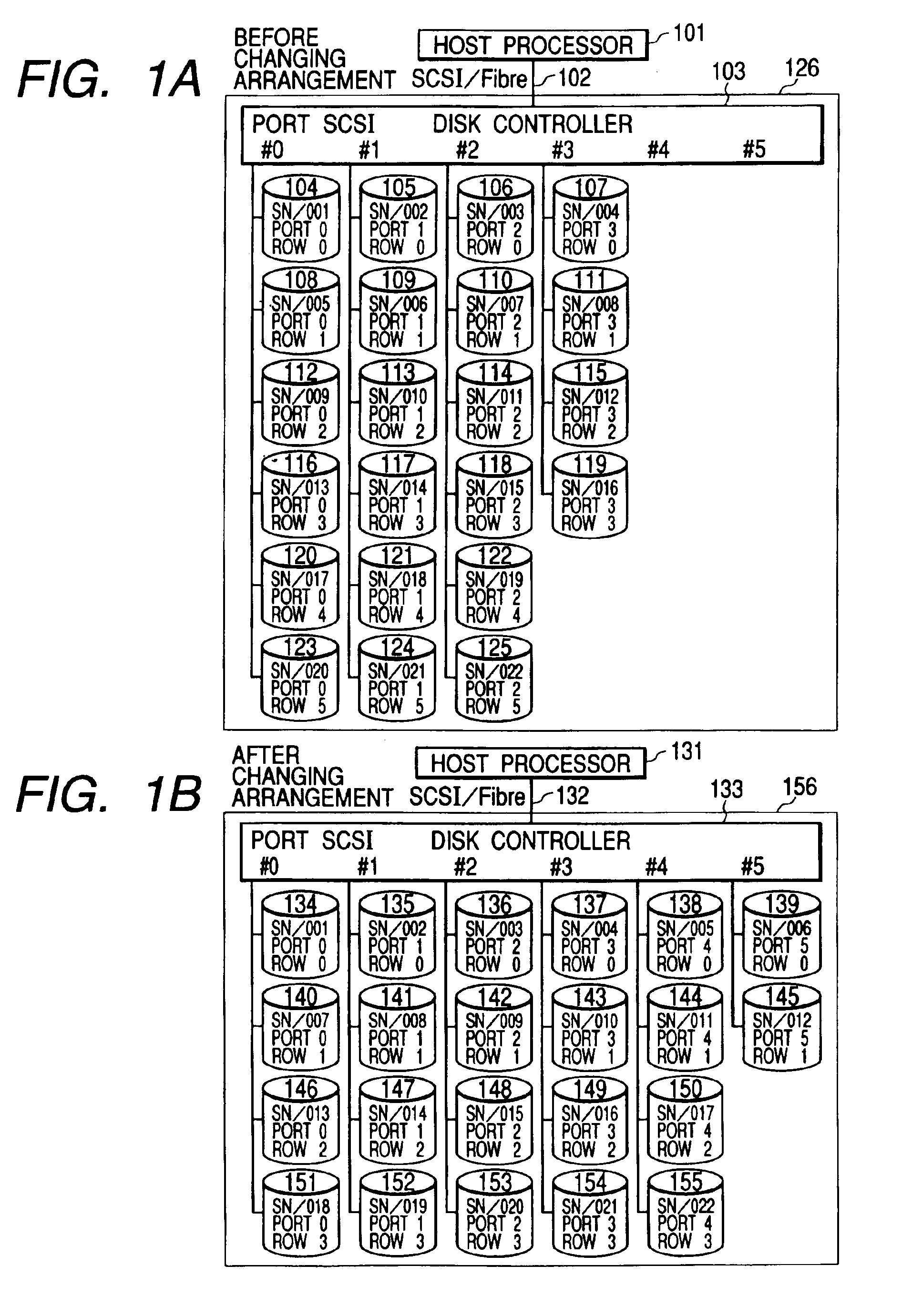
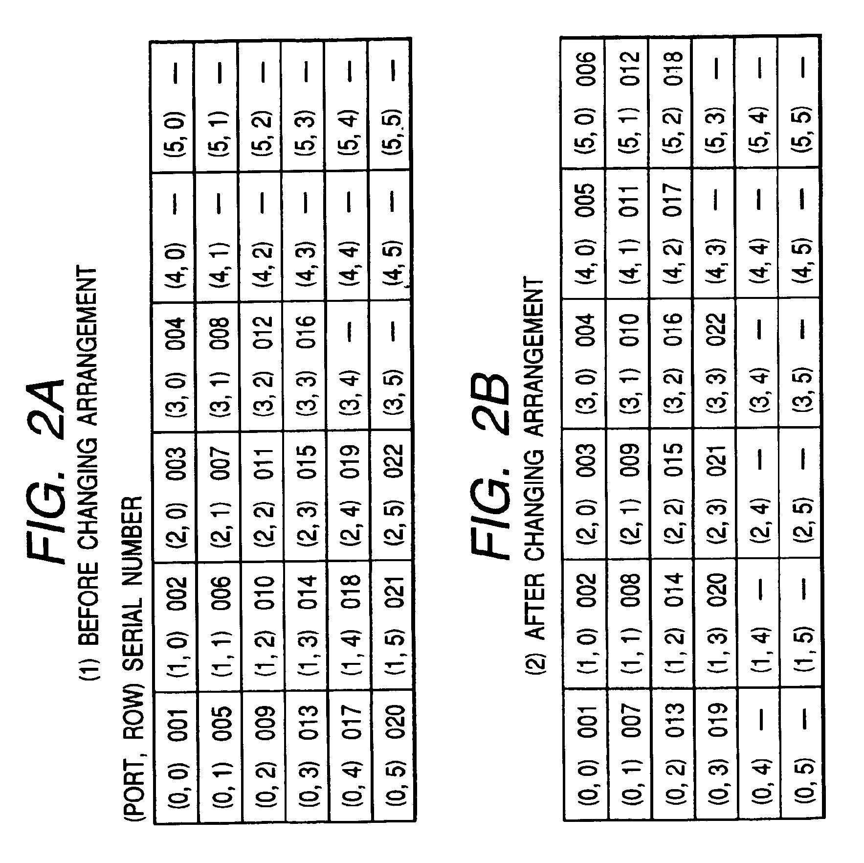
FIGS. 1A and 1B are diagrams each illustrative of an arrangement of hard disk units constituting a disk array system to which the present invention is applied. FIG. 1A shows an arrangement before arrangement-changing is not executed and FIG. 1B shows an arrangement after the arrangement-changing is executed. According to the present invention, even if the arrangement-changing is executed as shown in FIGS. 1A and 1B, data stored in the disk array system can be preserved without using any sheltering means such as means for backup. The example will hereinafter be described in detail.

FIGS. 1A and 1B are also illustrative of how connection is established between a host processor 101 and a disk array system 126. The host processor 101 and the disk array system 126 are connected to each other by means of SCSI or a fiber channel 102 as an interface....


PUM


Abstract

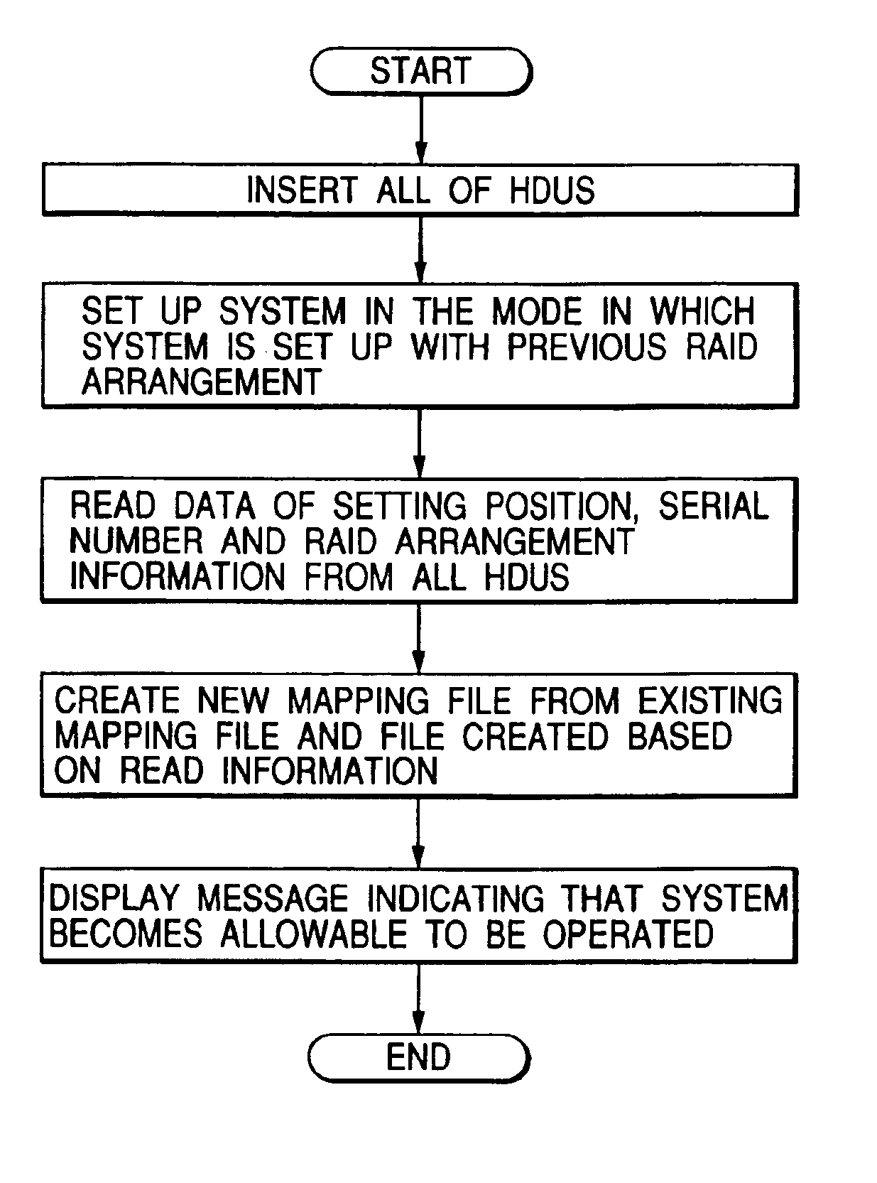
RAID information and physical position information of hard disk units are managed by a disk controller in a mapped fashion. When the physical position of the hard disk units is changed, the information mapping is retried. Further, the positional information of the hard disk units accommodated in a disk array system under the administration of the disk controller, is calculated so as to form n-dimensional coordinate system information, and the resulting information is stored in each of the hard disk units. When the hard disk units are inserted into the disk array system, the n-dimensional coordinate system information is read from each hard disk unit. If it is detected that there is difference from the current coordinate system information, then information before removal and that after the insertion are compared with each other and a data link is reconstructed.

Description

BACKGROUND AND SUMMARY OF THE INVENTIONThe present invention relates to a method of controlling hard disk units accommodated in a disk array system.A disk array system is ordinarily arranged to accommodate a plurality of hard disk units. One of the features of the disk array system utilized so far is that when any trouble is caused in the hard disk units accommodated in the disk array systems, the target hard disk unit is removed from the system and a hard disk unit with no failure is accommodated in the place where the problematic hard disk unit suffering from a problem is housed, whereby it becomes possible to restore the data stored in the system. For example, Gazette of U.S. Pat. No. 4,870,643 discloses a matter relating to the data restoration upon exchanging a hard disk unit.Further, according to the invention disclosed in Gazette of U.S. Pat. No. 4,870,643, it is assumed that, ordinarily, no more than one hard disk unit will become problematic at a time, so that it is unneces...

Claims


Application Information

Patent Timeline
Patent Type & Authority Patents(United States)
IPC IPC(8): G06F3/06
CPCG06F3/0601G06F2003/0697
Inventor SUZUKI, KATSUYOSHITAKAMOTO, KENICHIMURAOKA, KENJIIWASAKI, HIDEHIKO
Owner HITACHI LTD
Why Eureka
Eureka Blog
Learn More