Electronic intelligent turn signal control system
- Summary
- Abstract
- Description
- Claims
- Application Information
AI Technical Summary
Benefits of technology
Problems solved by technology
Method used
Image
Examples
Embodiment Construction
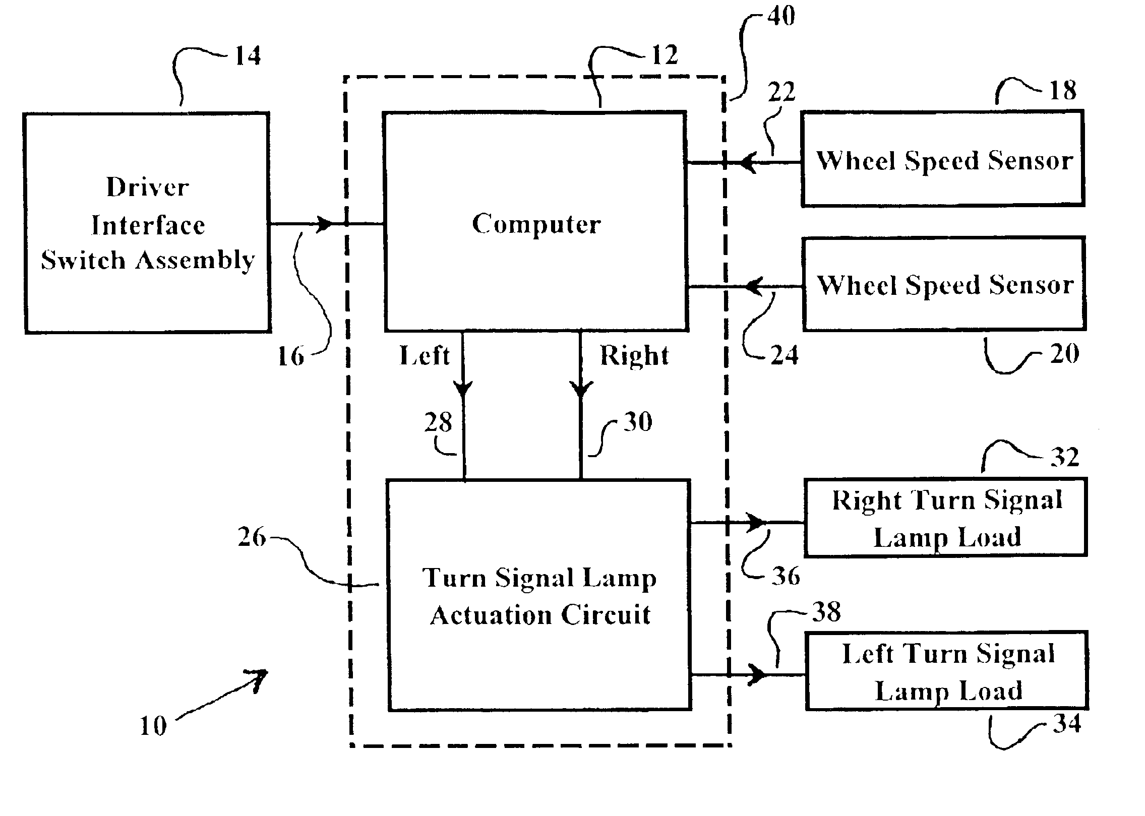
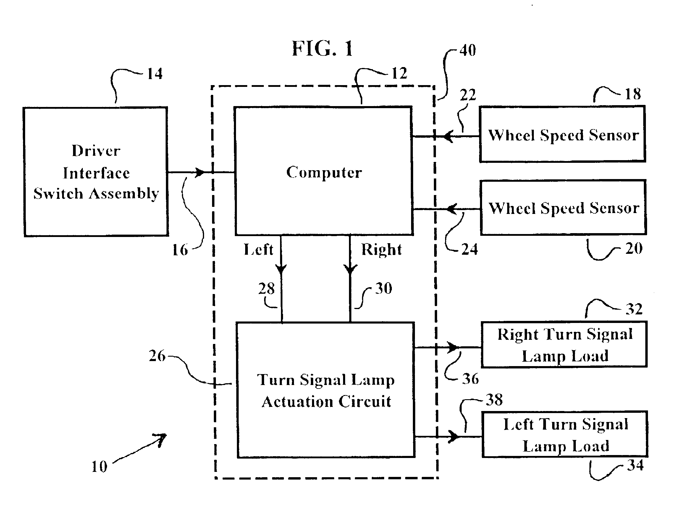
Referring now to the drawings, the intelligent turn signal control system 10 function block diagram in a vehicle is illustrated in FIG. 1. A computer, generally designated by the numeral 12, and can be of the type used in the art having a writeable, non-volatile memory for the storage of long term data and software programs which is operably connected to a vehicle to carry out the functions described herein. This computer 12 is equipped to determine the on / off status of the turn signal based upon inputs and computations. The actual turn signal flashing cycle, typically consisting of a 50% duty cycle on / off and 75 flash cycles per minute may be controlled by the computer 12 as well.
A driver interface switch assembly is designated by the numeral 14. This switch assembly 14 includes function controls for selecting the “right turn signal”, selecting the “left turn signal”, or selecting “cancel” which shuts off all turn signal function. These modes are each achieved by means of a momenta...
PUM
| Property | Measurement | Unit |
|---|---|---|
| Time | aaaaa | aaaaa |
| Angle | aaaaa | aaaaa |
| Angle | aaaaa | aaaaa |
Abstract
Description
Claims
Application Information
 - R&D
- Intellectual Property
- Life Sciences
- Materials
- Tech Scout
- Unparalleled Data Quality
- Higher Quality Content
- 60% Fewer Hallucinations
Browse by: Latest US Patents, China's latest patents, Technical Efficacy Thesaurus, Application Domain, Technology Topic, Popular Technical Reports.
© 2025 PatSnap. All rights reserved.Legal|Privacy policy|Modern Slavery Act Transparency Statement|Sitemap|About US| Contact US: help@patsnap.com


