
Waste treating method

a technology of waste treatment and waste, which is applied in the direction of combustible gas production, separation processes, products, etc., can solve the problems of increased heat resistance of the facility, difficulty in substantially and unpreferable high-temperature steam below 510° c. , to achieve the effect of reducing the amount of waste such as garbage safely and efficiently

Inactive Publication Date: 2005-04-05
TOYODA JIRO
View PDF23 Cites 19 Cited by
  • Summary
  • Abstract
  • Description
  • Claims
  • Application Information

AI Technical Summary

Benefits of technology

In a waste disposal method in accordance with a first invention for attaining the above object, wastes mainly containing any one or two or more of garbage, used tires, waste lumber, paper diapers, waste plastics, organic sludge, and human or animal excrement are exposed to high-temperature steam in an oxygen-free state while being stirred as necessary to be carbonized. Thereby, even if source substances for dioxin are contained in the wastes, the amount of wastes such as garbage can be reduced safely and efficiently with no fear of generating harmful substances, and moreover the carbonized wastes can be reused effectively for applications to fuel or the like.
Also, in a waste disposal method in accordance with a second invention, organic wastes containing much water (for example, 60% or more of water) is exposed to high-temperature steam in an oxygen-free state to evaporate water and further to carbonize the wastes. Thereby, dairy products such as yogurt and milk or the like or organic wastes generated in the manufacture process of these dairy products, which have often been thrown away wastefully, can be reduced in amount efficiently to facilitate subsequent handling, and also the wastes having been carbonized can be reused usefully as fuel or carbon materials.
It is preferable that the carbonized wastes be taken out into the air after the carbonized wastes are exposed to low-temperature steam (for example, 100 to 120° C.) to decrease the temperature thereof. Thereby, the wastes having been disposed of can be prevented from burning in the air.
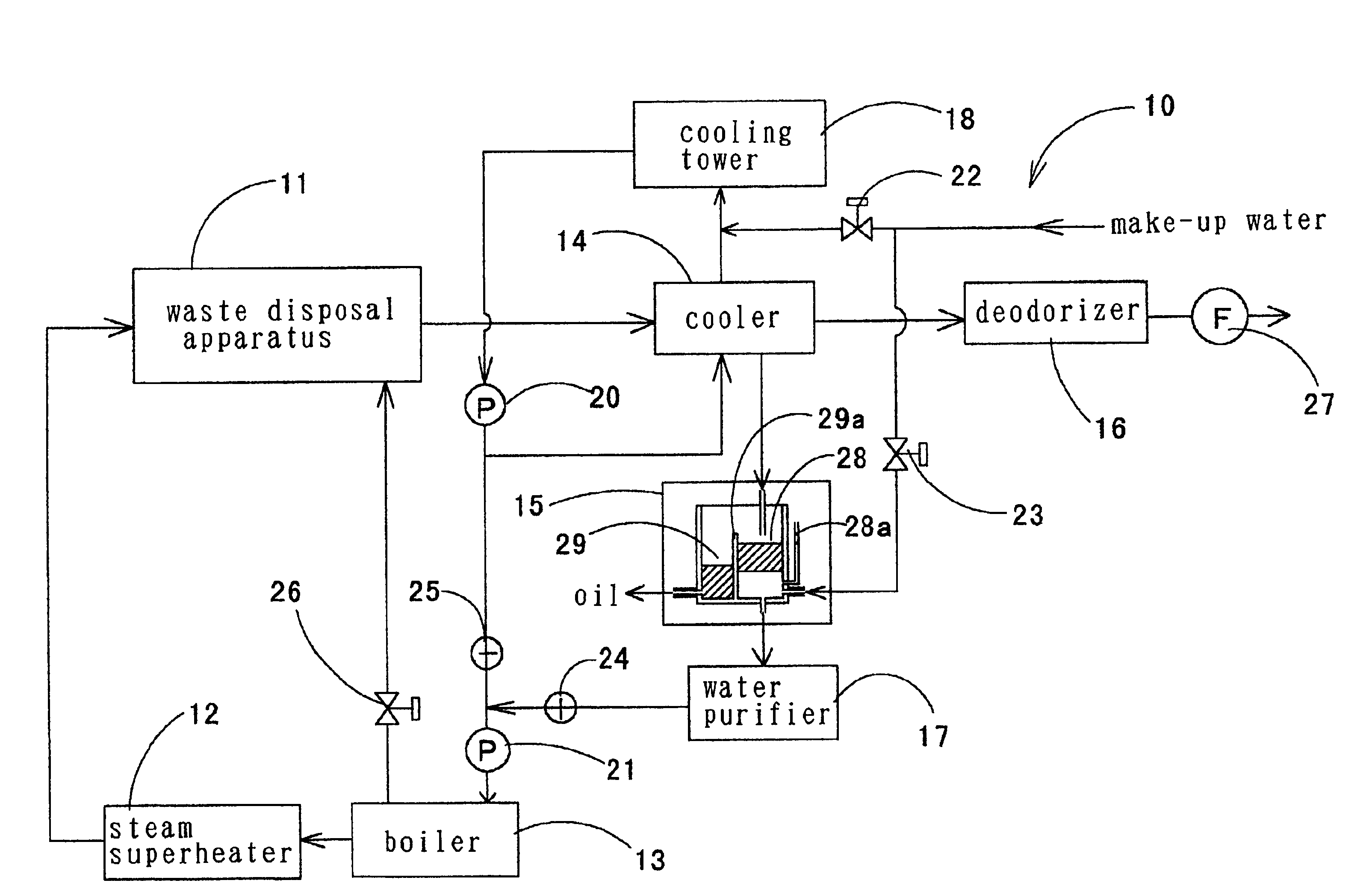
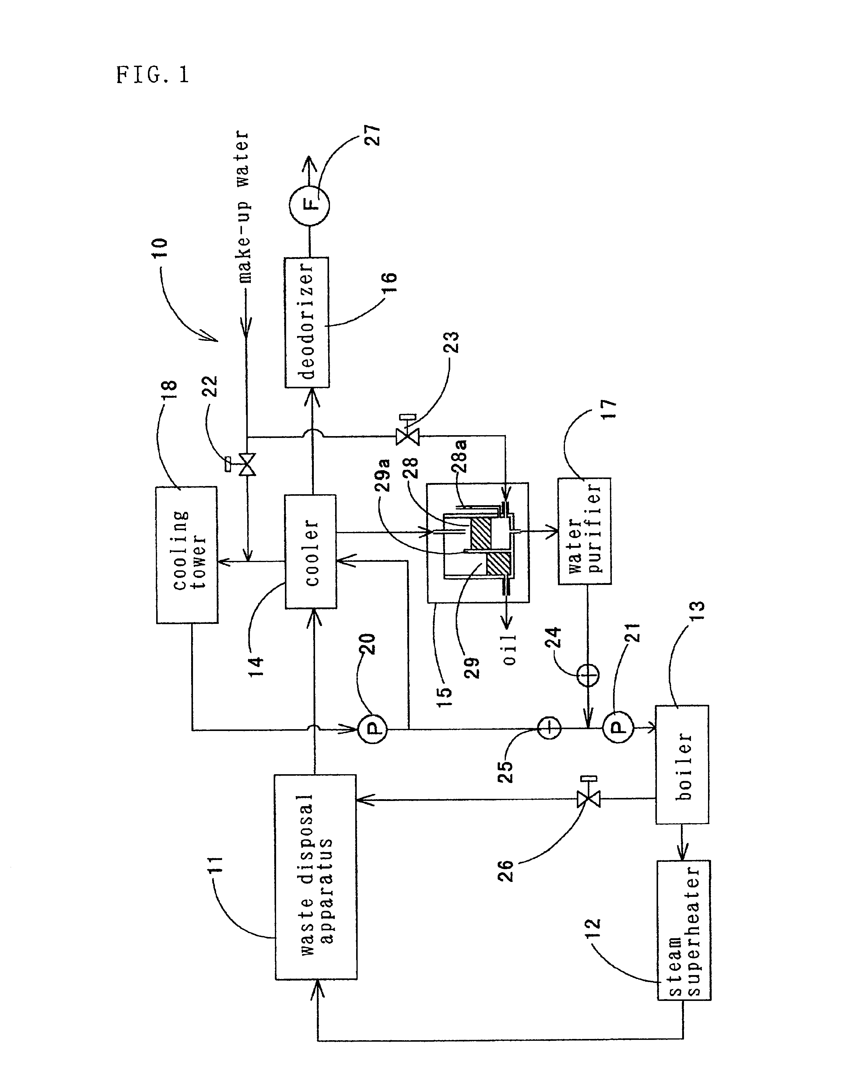
Also, it is preferable that the gas after disposal be cooled, water and oil contained in the gas be recovered, and the recovered water be returned to a boiler for generating feed steam of the high-temperature steam. Thereby, the recovered water and oil can be reused effectively, and also a clean environment can be maintained without releasing substances causing pollution in the surroundings of disposal facility. The garbage preferably contains waste food mainly. In this case, the oil contained in waste food is recovered and refined, by which the oil can be reused effectively as fuel oil, cooking oil, or the like.

Problems solved by technology

If the temperature of the high-temperature steam is lower than 510° C., it takes much time to carbonize garbage etc., so that it is difficult to carry out disposal substantially.
Therefore, the temperature of the high-temperature steam lower than 510° C. is unpreferable.
Inversely, in order to increase the temperature of the high-temperature steam to a temperature exceeding 900° C., a large amount of energy is needed, and moreover there are imposed many restrictions such that the heat resistance of facility used must be increased.

Method used


Image

  • Waste treating method
  • Waste treating method
  • Waste treating method

Examples


second embodiment

As shown in FIG. 3, a waste disposal apparatus 50 of a second embodiment includes a conveyor type transfer device 52 having a belt 51, a plurality of support members 53 provided on the belt 51 moving in the horizontal direction at a predetermined intervals, and buckets 54 each of which is hung by the support member 53 and into which wastes are put while the bucket 54 keeps its posture in a fixed direction. The waste disposal apparatus 50 can have a closed construction wholly or at a specific portion as necessary. Also, the waste disposal apparatus 50 is configured so that high-temperature steam of a predetermined temperature is blown along the waste charging direction by using the steam superheater 12, or the temperature in the apparatus can be controlled by blowing cooling steam etc. from the boiler 13. The bucket 54 and the belt 51 are constructed by many porous sections or meshes to cause steam to pass through easily, so that the wastes put into the bucket 54 and steam can effect...

third embodiment

As shown in FIGS. 4(a) and 4(b), a waste disposal apparatus 60 of a third embodiment is substantially disk shaped as a whole so that substantially fan shaped trays 61 in which wastes are put can be revolved on the horizontal plane, and includes a rotary table 62 on which the trays 61 are put, and a drive unit, not shown, for driving the rotary table 62. The waste disposal apparatus 60 can have a closed construction wholly or at a specific portion as necessary. Thereupon, the temperature of every portion on the rotary table 62 can be controlled so as to be a predetermined value by blowing high-temperature steam having been regulated to a predetermined temperature and a predetermined amount by the steam superheater 12 along the revolving direction of the tray 61 configured by many porous sections or meshes, or by blowing cooling steam etc. from the boiler 13. For example, the rotating motion period and the standstill period are repeated alternately, and during the standstill period, e...


PUM

PropertyMeasurementUnit
temperatureaaaaaaaaaa

Abstract

Wastes mainly containing any one or two or more of raw garbage, waste lumber, paper diapers, waste plastics, and organic sludge discharged from the food industry, common houses, etc. are exposed to high-temperature steam of 510 to 900° C. in an oxygen-free state, preferably while being stirred, to be carbonized. Thereby, the amount of wastes is reduced safely and efficiently with no fear of generating harmful substances such as dioxin, and moreover the carbonized wastes can be reused effectively for applications to fuel or the like.

Description

TECHNICAL FIELDThe present invention relates to a disposal method for wastes such as raw garbage generated in processing foods such as livestock meat, fish meat, and vegetables in food plants or during and after cooking in common houses, restaurants, etc., waste lumber, paper diapers, and waste plastics.BACKGROUND ARTConventionally, wastes such as raw garbage generated in common houses, restaurants, food plants, or the like have been collected at a collection yard, and then disposed of by incineration using fuel or by decomposition using microorganisms. Other wastes have been disposed of by incineration.However, in the disposal method using incineration and microorganisms, since the wastes are merely reduced in amount and subjected to land disposal etc., a problem arises in that wastes generated in large amounts cannot be reused effectively as a resource. Furthermore, in the disposal method by incineration, since plastic materials containing chlorine etc. are often contained in the ...

Claims


Application Information

Patent Timeline
Patent Type & Authority Patents(United States)
IPC IPC(8): C10J3/20C10B53/00C10J3/02C10B53/07
CPCC10B53/00C10B53/07C10J3/20C10J3/007C10J2300/169C10J2300/0946C10J2300/0976Y02P20/143
Inventor TOYODA, JIRO
Owner TOYODA JIRO
Learn More