
Active floor vibration control system

a technology of vibration control system and floor, applied in the field of vibration damping, can solve the problems of excessive or unwanted vibration, vibration can occur in many places including cars, planes, etc., and achieve the effect of improving the effectiveness of vibration control system and reducing the vibration in the floor

Inactive Publication Date: 2005-04-05
PENN STATE RES FOUND
View PDF20 Cites 25 Cited by
  • Summary
  • Abstract
  • Description
  • Claims
  • Application Information

AI Technical Summary

Benefits of technology

The invention is a system that controls floor vibrations in real-time using sensors, feedback controllers, and actuators. The system works by creating a feedback loop that generates a control force proportional to the velocity of the floor, which counteracts the motion of the floor. This results in damping of the controlled modes of floor vibration. The system is optimized to ensure that the motor can be driven with a sinusoidal force at any frequency without exceeding its capacity. The technical effect of this invention is to provide a more efficient and effective means of controlling floor vibrations in real-time, which can improve the overall performance and comfort of various applications such as vehicles, buildings, and sports arenas.

Problems solved by technology

Excessive or unwanted vibrations are common occurrences.
Such vibrations can occur in many places including cars, planes, elevators, and buildings.
Floor vibrations may be deemed as excessive if they impair the function of the building in some way.
At even very small levels, vibration can interfere with the operation of sensitive equipment.
When vibrations exist at levels above human perception, they can annoy or even alarm the occupants.
In offices and other quiet environments, vibration force levels as low as 0.005 g, where g is the acceleration of gravity, may yield complaints that people can't concentrate.
In terms of displacement, motion having peak amplitudes less than 1 mm can be a problem.
Above 0.02 g, people may start to question the safety of the structure and refuse to use the space.
Even though the structure is perfectly safe at this level of vibration, the perception of danger can still exist, thus impairing the function of the building.
Excessive floor vibrations are usually caused by either equipment or by normal occupant activities.
Occupant activities that have a repetitive motion, such as walking, dancing, and jumping, can cause objectionable floor motion due to resonance.
Damping is an effect that causes a dissipation of energy so that resonant vibrations cannot build to large levels.
At resonance, decreases in weight and damping result in higher vibration amplitudes given a certain level of disturbance.
Such decreases in weight and damping are occurring more often due to recent trends in building construction and use resulting in an increase in the instances of problem floor vibrations.
In some instances, owners of office buildings in successful service for 30 years are reporting problems that seem to be the result of a change from fully enclosed offices to cubicles.
Longer spans tend to vibrate at lower frequencies, thus resulting in natural frequencies more prone to resonance.
All of these trends lead to an increased likelihood of problem floor vibrations.
This type of isolation cannot be accomplished for occupant-induced vibrations caused by activities like walking, dancing and jumping so other modifications to the structure are often necessary to reduce the vibration.
While this action is typically very effective, it is not usually a good solution because the columns will disrupt the open space.
Additionally, if the columns do not run successively to the ground, they may transmit the vibration to other floors.
They can, however, transmit annoying vibrations to other parts of the building and interfere with the building space.
Additionally, they can be costly to build, disrupt occupants during installation, and may destroy the original purpose of the building design, for example if the original intent was to have a large open space for a cube-farm.
The drawbacks of adding concrete thickness include cost, inadequate strength to support the additional weight, disruption in an occupied building, and the need to modify interior walls, doors and plumbing.
Thus, this solution is probably not desirable except in extreme cases.
Effective stiffening of framing members, however, generally requires ceiling space below the floor structure that may not be available.
Accordingly, this solution has limited applicability and also suffers from the cost and disruption of building occupants.
The effectiveness of a tuned mass damper is limited by the amount of additional mass that can be safely supported by the structure.
Additionally, the mechanisms that provide the damping are often ineffective for very small amplitudes, thus rendering the device ineffective for all but the worst problem floors.
Active control technology has been used in many disciplines to improve the response of dynamic systems but has had limited impact in the case of floor systems.
The primary disadvantage is the increase in complexity and cost of implementing and maintaining the control system.
Several disadvantages of this system are that the properties of the actuator are not optimized for maximum control effectiveness and a computer-based control loop is not very practical for actual implementation.
This approach has the significant disadvantage of requiring multiple connections to the structure and the space for the device to hang.
However, the drawbacks to the traditional structural and passive solutions and the limited commercial success of the new active control systems illustrate the need for alternatives or improvements in controlling excessive floor vibrations.

Method used


Image

  • Active floor vibration control system
  • Active floor vibration control system
  • Active floor vibration control system

Examples


Embodiment Construction

Active control in this invention is implemented using a proof-mass actuator, a velocity sensor and a feedback loop to generate the control forces to add active damping to a floor system or other structure that exhibits excessive or unwanted vibrations. The core of the invention is not the combination of the three components, but in the inventor's discovery of the optimum interaction of the components to significantly increase the control efficiency above prior art methods. The improved performance is based on the design of each of the components that make it possible to collectively work as an effective and efficient control system for floor systems.

Each component of the active damping system will now be discussed in more detail:

Velocity Sensor: The first component of the system is a velocity or similar sensor that can sense vibration amplitude (velocity). The sensor needs to be capable of generating a time dependant voltage that is proportional to, and in phase with, the velocity o...


PUM


Abstract

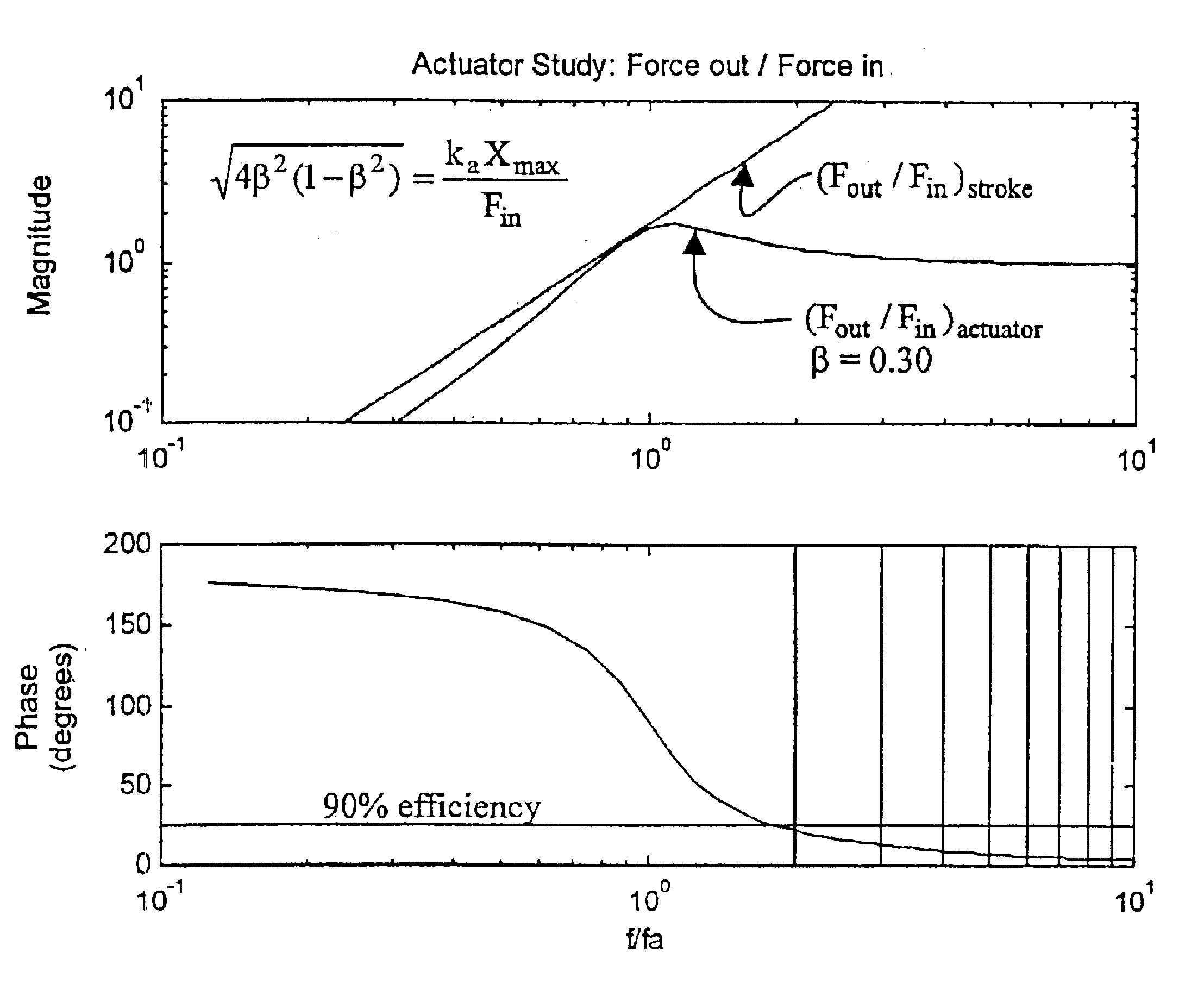
An active vibration control system for controlling excessive or unwanted vibrations in floors or other structures. The system has three main components: (1) velocity sensor w / signal conditioner; (2) feedback controller; and (3) proof-mass actuator. This system works by creating a feedback loop that generates a control force proportional to the velocity, thus adding damping to the controlled modes of floor vibration. In other words, the feedback loop makes the moving mass of the actuator move to counteract the motion of the floor. The system is optimized such that the motor can be driven with a sinusoidal force where the peak force is at or near the full motor capacity at any frequency without exceeding the stroke while maintaining a simple and cost effective feedback controller. Additionally, a relationship between the fundamental natural frequency of the floor system and actuator is established to provide efficient and stable control.

Description

FIELD OF THE INVENTIONThe present invention relates to the field of vibration damping. More particularly the invention relates to active control systems containing (1) velocity sensor, (2) feedback controller, and (3) proof-mass actuator and their use for damping vibrations of floors and other structures.BACKGROUND OF THE INVENTIONExcessive or unwanted vibrations are common occurrences. Such vibrations can occur in many places including cars, planes, elevators, and buildings. Controlling unwanted vibrations is a diverse area with many different applications and techniques. One specific area of concern to the present inventor is vibration that may occur in the floors of buildings.Floor vibrations may be deemed as excessive if they impair the function of the building in some way. At even very small levels, vibration can interfere with the operation of sensitive equipment. When vibrations exist at levels above human perception, they can annoy or even alarm the occupants. In offices and...

Claims


Application Information

Patent Timeline
Patent Type & Authority Patents(United States)
IPC IPC(8): E04F15/22E04B1/98F16F7/10
CPCF16F7/1005E04B1/985E04F15/22B60G2202/25B60G2204/128B60G2400/206B60G2400/91B60G2800/916B60G2800/162E04H9/0215F16F2228/001F16F15/002
Inventor HANAGAN, LINDA M.
Owner PENN STATE RES FOUND
Learn More