
Integrated receiving/backscattering arrangement for contactless data transmission

a contactless data and receiving/backscattering technology, applied in the direction of mechanical actuation of burglar alarms, using reradiation, instruments, etc., can solve the problems of not being advantageous in view of tunability and quality factor, and achieve the effect of improving the signal to noise ratio of a psk and increasing the communication rang

Inactive Publication Date: 2005-03-22
ATMEL DEUT +1
View PDF12 Cites 28 Cited by
  • Summary
  • Abstract
  • Description
  • Claims
  • Application Information

AI Technical Summary

Benefits of technology

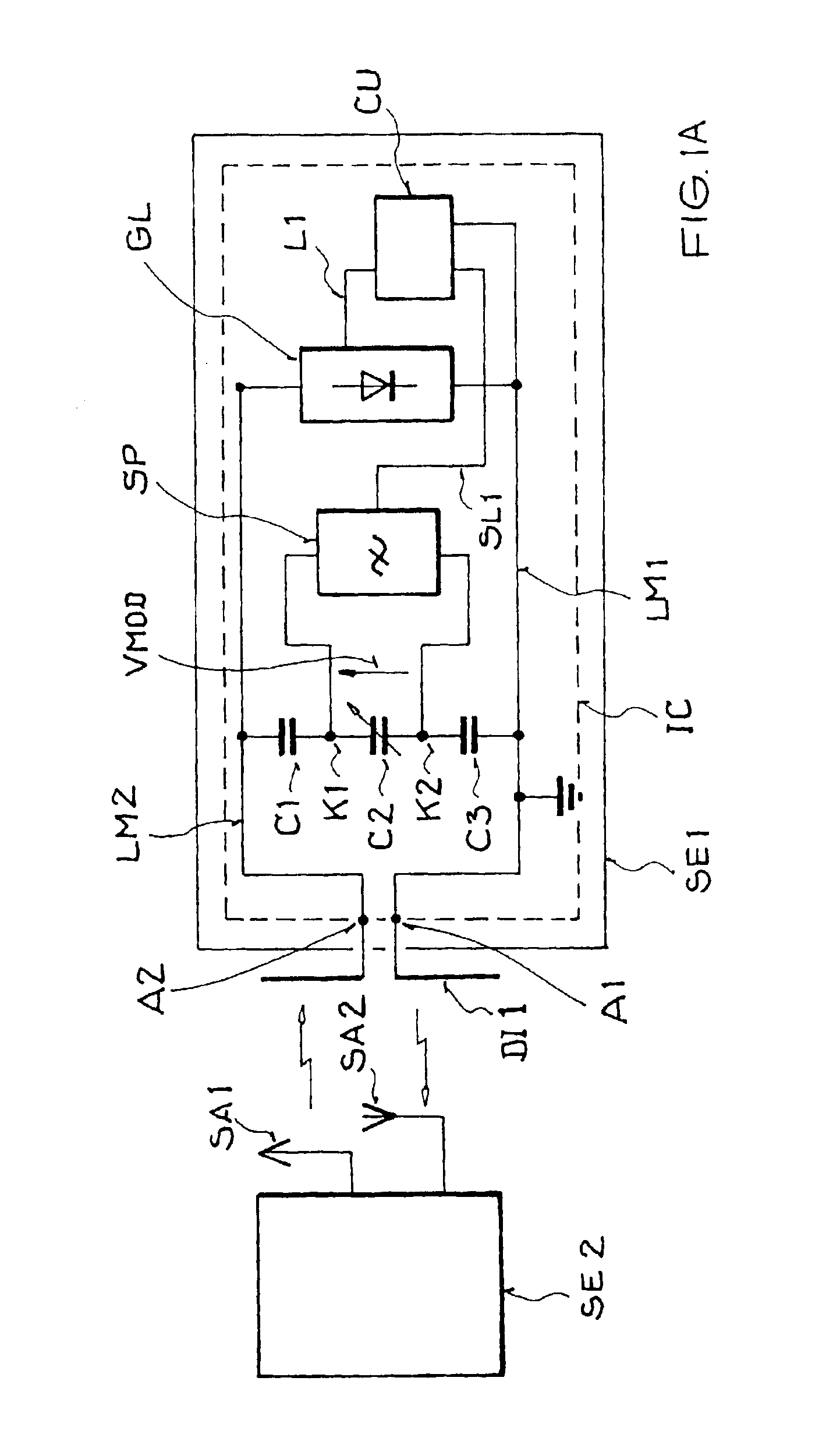
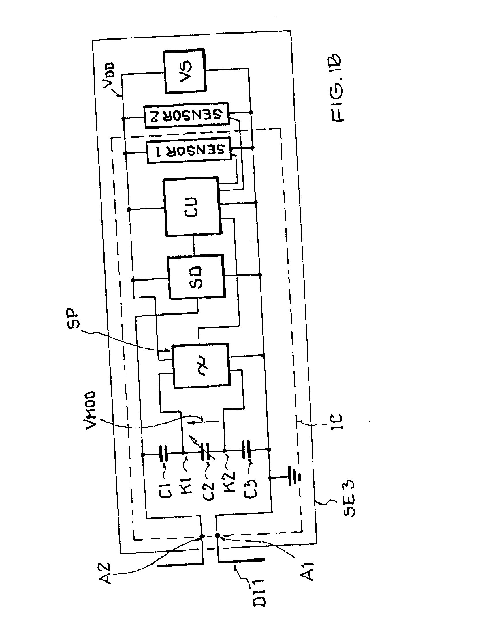
The invention provides a receiving and backscattering arrangement for contactless data transmission that has high efficiency and a long communication range. It achieves this by easily varying the impedance of the input antenna circuit with low losses. The arrangement uses a series arrangement of three capacitances, with a variable capacitance varactor in the middle. The use of a controllable gate capacitance, particularly a CMOS varactor, ensures that the varactor is DC-decoupled from the antenna contacts and achieves a high quality factor. The arrangement also minimizes parasitic losses in the high frequency range, increases the quality or Q factor of the antenna resonant circuit, and reduces the costs for fabrication. The impedance of the MOS varactor can be varied effectively for data transmission in the high frequency range, and the use of a third conductive layer on the semiconductor substrate further improves the arrangement's performance.

Problems solved by technology

While the use of a controllable gate capacitance would be CMOS compatible, it is not as advantageous in view of the tunability and the quality factor (e.g. due to losses through the structure, and consequent transmission range limitations).

Method used


Image

  • Integrated receiving/backscattering arrangement for contactless data transmission
  • Integrated receiving/backscattering arrangement for contactless data transmission
  • Integrated receiving/backscattering arrangement for contactless data transmission

Examples


Embodiment Construction

FIG. 1A schematically shows a high frequency communication system for carrying out a bi-directional contactless data transmission, including a transmitter / receiver device SE2, for example a base station, and a receiving / backscattering arrangement SE1, for example a passive transponder. The transmitter / receiver device SE2 emits an interrogation or inquiry signal through a transmitting antenna SA1. This signal is received by the antenna of the receiving / backscattering arrangement SE1, where it is modulated, and backscattered as a response or answer signal. Then, the backscattered response signal is received by the transmitter / receiver device SE2 through a receiving antenna SA2. The transmitter / receiver device SE2 can have any conventionally known structure and operation for transmitting and receiving the signals as described herein. The invention is particularly directed to the construction of the receiving / backscattering arrangement SE1, which will now be described in detail.

The rece...


PUM


Abstract

A receiving / backscattering arrangement for carrying out a contactless data transmission includes an integrated circuit having two antenna contacts, a series arrangement of three high quality capacitances connected between the two antenna contacts, whereby the middle capacitance is an MOS varactor, a controllable variable voltage source connected across the MOS varactor, and a control unit that controls the voltage source. The receiving / backscattering arrangement is especially a passive transponder with a rectifier connected between the antenna contacts, or a semi-passive transponder including a battery or solar cell, to provide the required supply voltage for the circuit. The arrangement achieves a large communication range, for receiving and modulating an interrogation signal, and backscattering the modulated response signal with a high efficiency and low losses. The integrated circuit structure is compact and economical.

Description

PRIORITY CLAIMThis application is based on and claims the priority under 35 U.S.C. §119 of German Patent Application 101 58 442.3, filed on Dec. 1, 2001, the entire disclosure of which is incorporated herein by reference.FIELD OF THE INVENTIONThe invention relates to a receiving and backscattering arrangement that receives and modulates an interrogation signal, and reflects or backscatters the modulated signal as an answer or response signal, to carry out a contactless data transmission.BACKGROUND INFORMATIONA receiving and backscattering arrangement of the above mentioned general type is known from the published European Patent Application 0,599,143 A2. In the known arrangement, a phase modulation of the received signal is carried out by means of the voltage controlled capacitance of a varactor. Thereby, an interrogation, polling or inquiry signal transmitted by a first interrogation device is received and backscattered as a response or answer signal by the answering device. A disa...

Claims


Application Information

Patent Timeline
Patent Type & Authority Patents(United States)
IPC IPC(8): G01S13/00G01S13/75G06K19/07G06K19/077
CPCG01S13/756G01S13/758G06K19/07764G06K19/0723G06K19/07749G06K19/0716H02J50/20H02J50/001
Inventor FISCHER, MARTINFRIEDRICH, ULRICHKARTHAUS, UDOZIEBERTZ, DIRK
Owner ATMEL DEUT
Learn More