Two-piece electrical RF shield and method of manufacturing the same

Inactive Publication Date: 2005-03-22
INTERPLEX IND
View PDF7 Cites 59 Cited by
  • Summary
  • Abstract
  • Description
  • Claims
  • Application Information

AI Technical Summary

Benefits of technology

The present invention is for a two-piece RF interference shield and method of manufacturing the same that is cost efficient and easily adapted for use with existing electrical devices. The RF shield includes a bottom portion mounted to the circuit board and a top portion which fits onto the bottom portion. The RF electrical interference shield can be mounted to circuit boards (e.g., by soldering) to prevent electrical components from causing RF interference. The RF shield of the present invention also allows for easy removal of the top of the RF shield so as to provide access to the interior for rework or repair of the electrical components covered by the shield, without having to unsolder the bottom portion of the shield.
The removable top portion forms the top side of the two-piece RF shield and completes the protective enclosure. The top portion includes a top face having a raised portion, as well as four downwardly extending sidewalls. Alternatively, the top portion may include two opposing downwardly extending sidewalls. The raised portion of the top portion allows an extraction tool to be utilized so that the top portion can be easily disengaged from its connection to the bottom portion. Two of the top portion sidewalls contain the barbs that protrude inwardly toward the bottom portion. The barbs along the two sidewalls of the top portion fit or snap into the corresponding holes or slots of the bottom portion. The sidewalls of the top portion extend downwards, perpendicularly, from the top face and have angled extensions at their bottom edges. The angled extensions of the sidewalls cooperate with an extraction tool to remove the top portion, thereby allowing access to the circuit board underneath. Specifically, the extraction tool pushes down on the raised portion causing the angled extensions to deflect outwardly disengaging the barbs from the slots. Simultaneously, the top cover can be removed by lifting the extraction tool who's side arms are beneath the angled extensions. Similarly, the top portion can be placed back onto the bottom portion by pushing the raised portion of the top portion downward towards the bottom portion and allowing the barbs on the top portion to fit or snap into the holes of the bottom portion.
In accordance with another embodiment of the, invention, the barbs, for snap-fitting the bottom and top portions, may be located on the bottom portion and protrude outwards from the bottom portion towards the top portion. The top portion can be adapted so as to contain holes or slots that correspond in number and location to the barbs of the bottom portion. The extraction tool would serve the same purpose as previously mentioned, however under this alternative design the barbs of the bottom portion remain stationary while the holes of the top portion move outwardly away from the barbs of the bottom portion thus allowing for the desired removal.

Problems solved by technology

This has caused an increase in the complexity and operation of the electrical components found in such devices and a decrease in the amount of space available for such components.
In such electrical devices, many electronic components radiate electromagnetic radiation which may cause interference with other electrical devices.
This RF interference may detrimentally affect the performance and operation of other electrical devices.
Over time, the circuit board may require repair or reworking, however, it is extremely time consuming and difficult to unsolder and remove the RF shield originally in place.
While there are existing two-piece designs, most are expensive and difficult to disassemble.

Method used


Image

  • Two-piece electrical RF shield and method of manufacturing the same
  • Two-piece electrical RF shield and method of manufacturing the same
  • Two-piece electrical RF shield and method of manufacturing the same

Examples


Embodiment Construction

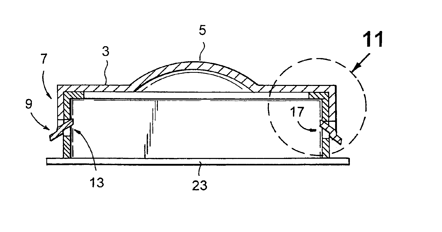
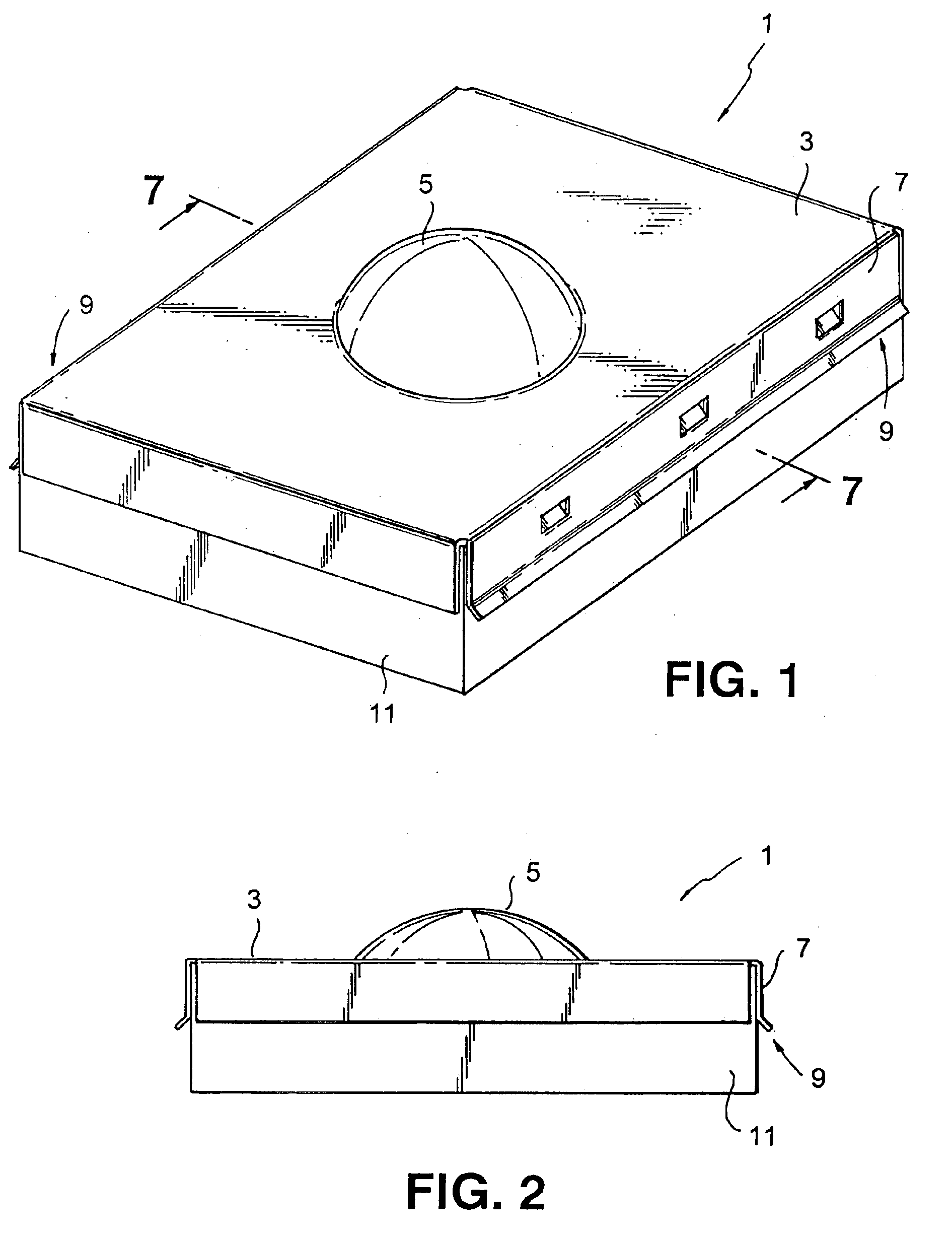
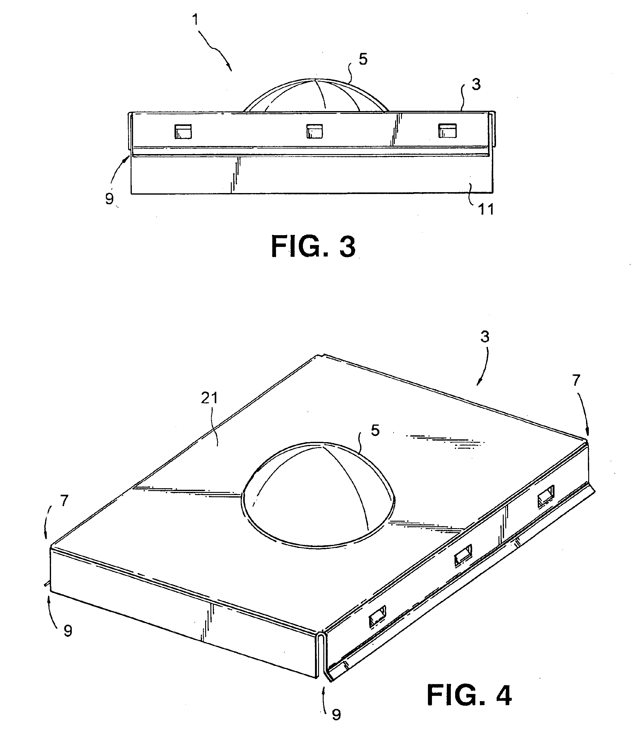
Referring now to the drawings, the present invention is directed to a two-piece RF interference shield illustrated, in perspective view, generally at 1 in FIG. 1. FIG. 1. shows an assembled RF shield 1 wherein the top portion 3 has been fitted to the bottom portion 11. FIGS. 2 and 3 show side views of the assembled RF shield 1. The RF shield 1 is manufactured according to conventional practices by stamping the RF shield 1 from a piece of metal using a die. After the assembly of electrical components on the PCB using conventional practices, the bottom portion 11 of the RF shield 1 is placed over the electrical components and soldered onto the PCB such that the components are within the cavity of the bottom portion 11.

In the preferred embodiment shown, the RF shield 1 is a two-piece design having both a bottom portion 11 and a top portion 3. The unassembled bottom portion 11 is illustrated, in perspective view, in FIG. 6. The unassembled top portion 3 is illustrated, in perspective vi...


PUM


Abstract

A two-piece RF interference shield and method of manufacturing the same that is cost efficient and easily adapted for use with existing electrical devices. The RF shield includes a bottom portion mounted to the circuit board and a top portion which fits onto the bottom portion. The RF electrical interference shield can be mounted to circuit boards (e.g., by soldering) to prevent electrical components from causing RF interference. The RF shield of the present invention also allows for easy removal of the top of the RF shield so as to provide access to the interior for rework or repair of the electrical components covered by the shield, without having to unsolder the bottom portion of the shield. The two-piece shield for shielding an electrical component comprises a top portion and bottom portion that are fitted together so as to enclose the electrical components to be shielded. The top and bottom portions snap together, e.g., by way of barbs located on one of the portions that fit into corresponding holes or slots located on the other portion.

Description

FIELD OF THE INVENTIONThe present invention generally relates to the field of electronics, and more specifically to a Radio Frequency (RF) interference shield for electrical devices.BACKGROUND OF THE INVENTIONOver the past number of years, the technological advancements in the area of electronic devices has experienced vast growth. For example, while cellular phones are becoming smaller and lighter, simultaneously their features and capabilities are expanding. This has caused an increase in the complexity and operation of the electrical components found in such devices and a decrease in the amount of space available for such components. In such electrical devices, many electronic components radiate electromagnetic radiation which may cause interference with other electrical devices. This RF interference may detrimentally affect the performance and operation of other electrical devices. As a result, RF shields have been used to prevent such components from causing such interference.T...

Claims


Application Information

Patent Timeline
IPC IPC(8): H05K9/00
CPCH05K9/0032
Inventor SEIDLER, JACK
Owner INTERPLEX IND
Why Eureka
Try Eureka