
Lubricating coating composition suitable for lubrication of a threaded joint

a technology of lubricating coating and threaded joints, which is applied in the direction of screw threaded joints, hose connections, mechanical equipment, etc., can solve the problems of affecting the operation efficiency of the machine, affecting the lubrication effect of the machine, so as to improve the lubrication effect. , the effect of good correlation

Inactive Publication Date: 2005-03-22
VALLOUREC OIL & GAS FRANCE SAS +1
View PDF20 Cites 50 Cited by
  • Summary
  • Abstract
  • Description
  • Claims
  • Application Information

AI Technical Summary

Benefits of technology

[0021]Another object of the present invention is to provide a lubricating coating composition which is capable of preventing or alleviating the formation of rust without using a compound grease, thereby improving the stability of make-up torque.
[0040]Furthermore, when the lubricating coating composition of the present invention is applied to a threaded joint for oil well pipes, it forms a lubricating coating which continues to exhibit a lubricating function even when make-up and break-out are repeated. This lubricating coating contains at least 10 wt % of the basic lubricant as a main lubricant, and even when it does not include another lubricant such as a base oil, it can exhibit a lubricating effect.

Problems solved by technology

However, compound grease contains a large amount of a powder of a heavy metal such as Pb, Zn, or Cu, and when the applied grease is washed off, there is the possibility of its causing environmental pollution.
In addition, the application of compound grease worsens the work environment and decreases the operating efficiency.
However, it is not easy to form a solid lubricant-resin coating to a uniform thickness along the shape of the thread and the unthreaded metal contact portions of a threaded joint.
If the coating is not formed with a prescribed uniform thickness, in those areas where the coating is too thick, the surface pressure exerted thereon during fastening of the threaded joint becomes too large, resulting in an increase in the torque required for fastening (make-up torque), or this may lead to deformation of the shape of the threads, and it becomes easy for galling to occur.
On the other hand, in areas where the coating is too thin, poor lubrication and rusting tend to occur easily.
In addition, when an oil well pipe is stood upright, rust or scale flakes peeled off from the internal surface or blasting particles introduced to remove rust or scale may fall down through the lumen of the pipe and adhere or deposit on the joint.
Thus, fastening may take place in the presence of rust or scale flakes or blasting particles adhered on the threaded portion or the unthreaded metal contact portion.
This is because a solid lubricant-resin coating has poor extensibility and fluidity, and it may easily peel off.
Under the above-described conditions, an excessive pressure may be applied locally on some areas in the threaded portion and unthreaded metal contact portion, thereby causing the solid lubricant-resin coating to peel off in the excessively pressurized areas.
Thus, bare metal surfaces may be exposed in some areas of the joint, leading to the occurrence of galling.
This effect cannot be expected with a solid lubricant-resin coating which inherently has poor extensibility and fluidity.
In contrast, a solid lubricant-resin coating is formed prior to the initial fastening operation and should be maintained up to the last fastening operation, so it has a problem with respect to rust prevention as described below.
The resulting oil well pipe / coupling member assembly has a pin or box at each end which is not connected to a mating box or pin, and such a pin or box is often exposed to rain water during transport or during storage.
The solid lubricant-resin coating does not have sufficient rust preventing properties to completely protect the pins and boxes in such situation and rusting can easily occur.

Method used


Image

  • Lubricating coating composition suitable for lubrication of a threaded joint
  • Lubricating coating composition suitable for lubrication of a threaded joint
  • Lubricating coating composition suitable for lubrication of a threaded joint

Examples


examples

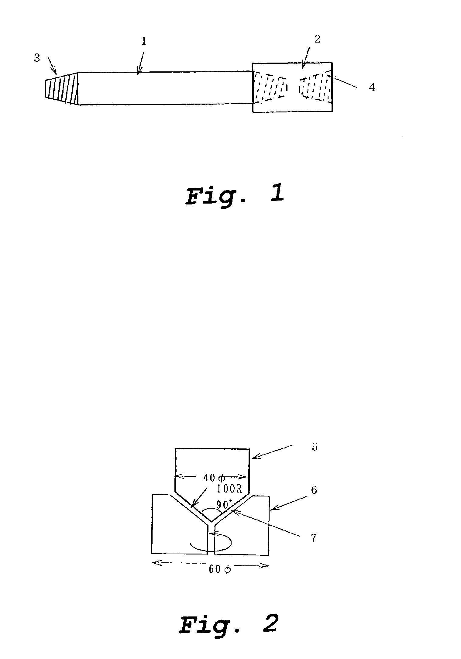
[0138]In the following Examples, lubricity of a lubricating coating was evaluated by a test using a rotating friction tester as shown in FIG. 2. This test has been confirmed to have a good correlation with a fastening test on a threaded joint of an oil well pipe. In this test, a pair of a mating convex and concave test pieces 5, 6 are used. The convex test piece 5, to which a controlled load can be applied, corresponds to a pin and has an end with a conical shape. The concave test piece 6, which can be rotated at a controlled speed, corresponds to a box and has a recess with the same conical shape as the convex test piece 5. The two test pieces were made of the same steel, which was either an Mn steel (a carbon steel) or a 13Cr steel (a stainless steel) having the composition shown in Table 1, both of which are actually used in the manufacture of oil well pipes and coupling members. The mating or contact surfaces 7 of the test pieces had a lubricating coating formed thereon for eval...


PUM

PropertyMeasurementUnit
Lengthaaaaaaaaaa
Massaaaaaaaaaa
Surface roughnessaaaaaaaaaa

Abstract

A lubricating coating composition in which at least one basic lubricant selected from a basic sulfonate, a basic salicylate, and a basic phenate is dissolved in a volatile solvent is applied to the frictional surface of a box and a pin constituting a threaded joint for oil well pipes. The composition may further contain one or more of a thermoplastic resin powder, another lubricant, and an extreme pressure agent. The surface roughness of the frictional surfaces preferably has an Rmax in the range of 5-40 micrometers.

Description

[0002]This application is a continuation of International Application No. PCT / JP01 / 10573 filed on Dec. 4, 2001 and claims priority under 35 U.S.C. §§ 119 and / or 365 to 2000-368895 filed in Japan on Dec. 4, 2000, the entire content of which is hereby incorporated by reference.TECHNICAL FIELD[0003]This invention relates to a lubricating coating composition suitable for lubrication of a threaded joint for metal pipes and particularly oil well pipes, and to a method of lubricating a threaded joint using the composition. The lubricating coating composition according to this invention can impart adequate lubricity and rust preventing properties to a threaded joint for oil well pipes without the need to apply a lubricating grease.BACKGROUND ART[0004]Oil well pipes such as tubing and casing used in the drilling of oil wells for crude oil and gas oil are typically connected to each other by threaded joints. In the past, the depth of oil wells was typically 2000 to 3000 meters, but more recen...

Claims


Application Information

Patent Timeline
IPC IPC(8): C10M111/04C10M169/04C10M159/00C10M165/00C10M111/00C10M167/00C10M159/20C10M169/00E21B17/042E21B17/02F16L15/04F16L15/00C10M109/02C10M121/02C10M129/16C10M135/06C10M135/20C10M137/02C10M137/04C10M137/10C10M143/02C10M143/04C10M143/16C10M145/14C10M149/18C10M159/22C10M159/24C10N10/04C10N10/12C10N20/00C10N20/06C10N30/06C10N30/12C10N40/00C10N40/34C10N50/02
CPCC10M111/04F16L15/004C10M165/00C10M167/00C10M169/042C10M169/047C10M169/048F16L58/182C10M159/20C10M2203/065C10M2203/1006C10M2205/022C10M2205/0225C10M2205/024C10M2205/04C10M2205/043C10M2207/028C10M2207/0285C10M2207/126C10M2207/262C10M2207/2623C10M2207/289C10M2207/40C10M2209/084C10M2209/0845C10M2217/044C10M2219/044C10M2219/046C10M2219/0463C10M2219/089C10M2223/04C10M2223/045C10N2210/02C10N2220/082C10N2230/06C10N2230/12C10N2230/52C10N2250/121C10N2280/00C10N2010/04C10N2020/06C10N2030/06C10N2030/12C10N2050/02C10N2080/00C10N2030/52
Inventor GOTO, KUNIONAGASAKU, SHIGEOYAMAMOTO, HIDEO
Owner VALLOUREC OIL & GAS FRANCE SAS
Learn More